Note: All of these Arduino IDE startup steps are done with the Qbot connected to the computer with the USB to micro USB cable. The power switch on the Qbot is OFF (to the left). The charging LED to the left of the micro USB port on the Qbot will show either red or green, doesn't matter which. There may be some other LEDs shining or flashing on the Qbot but they are not relevant here.
Step 1:
When you start up the Arduino IDE (Integrated Developer Environment) you will get a tool bar that looks something like this..
I don't remember what window it opens the very first time you use the IDE. Whatever the window is the code in that window is known as a sketch (a program really). The first thing we are going to do is get a different sketch to work with.
Step 2:
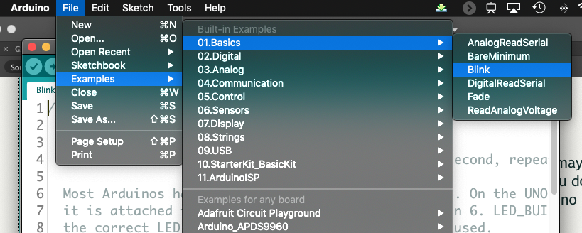
Go to the drop down File menu and choose File > Examples > Basics > Blink. Then close whatever the original window was. Here is what you will see as you select the Blink sketch...
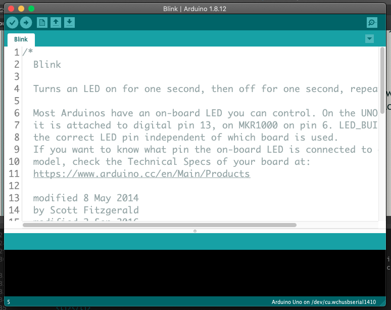
The window showing the Blink Sketch will look like this....
Step 3:
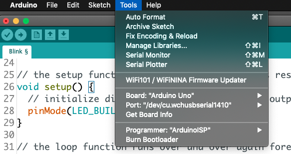
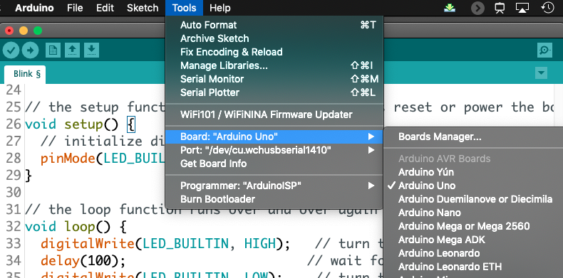
The next thing we need to do is check that the IDE software knows (recognizes) the Qbot that you have connected to your computer's USB port. To do this we go to the Tools menu and look near the bottom where it shows Board: , Port: , and Board Info. The IDE may have automatically recognized your Qbot or perhaps not. We will check that in a minute.
If the 'Board:' is not set to Arduino Uno select the Board: drop down menu and choose Arduino Uno from the list (there will be many many choices).
The port setting is often inscrutable. Select the port menu and consider your options (mine are below)
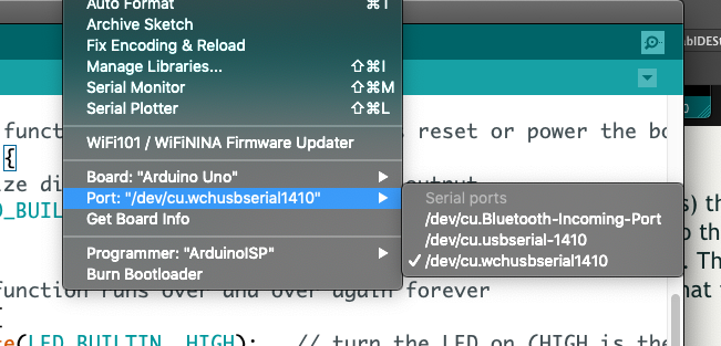
On a PC the ports are usually labelled COMM1 or some other number. On Mac's they often have usbserial in the name. Because the Qbot has a Bluetooth interface you will probably see a Bluetooth port labelled. Choose one of the USB ports (NOT the Bluetooth port) and then we'll test it.
Step 4:
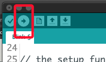
Testing the 'Port:' setting. At the top left of your sketch window there are 5 'buttons. A check mark, a right arrow, and 3 buttons that have to do with saving and opening sketchs. The check is a tool for checking to see if the code we have written is properly written (it can still do something we don't want!). This is sort of like spell checkers making sure we spelled the word right but not making sure what we've written makes sense. The 'right arrow' is the upload button which is the one we need right now. When we select this button the IDE checks our code (same process as the check mark) and then tries to send the code to the kind of board we chose in Board: on the port we chose on Port: Here is where the button is....
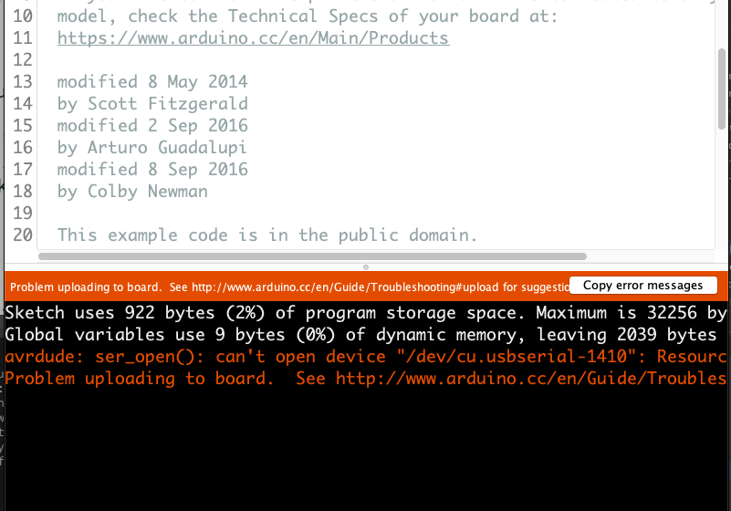
...and this is what your sketch window will look like if things go WRONG! Always best to show what goes wrong first. Look further down to see what it will look like if the port works. The error message that you see tells you the IDE tried to send the sketch where you told it to (the port) and there was nothing there to receive it. If you get this error message go back and change the port setting to a different port. One of the ports should work if your Qbot is attached to a USB port on your computer.
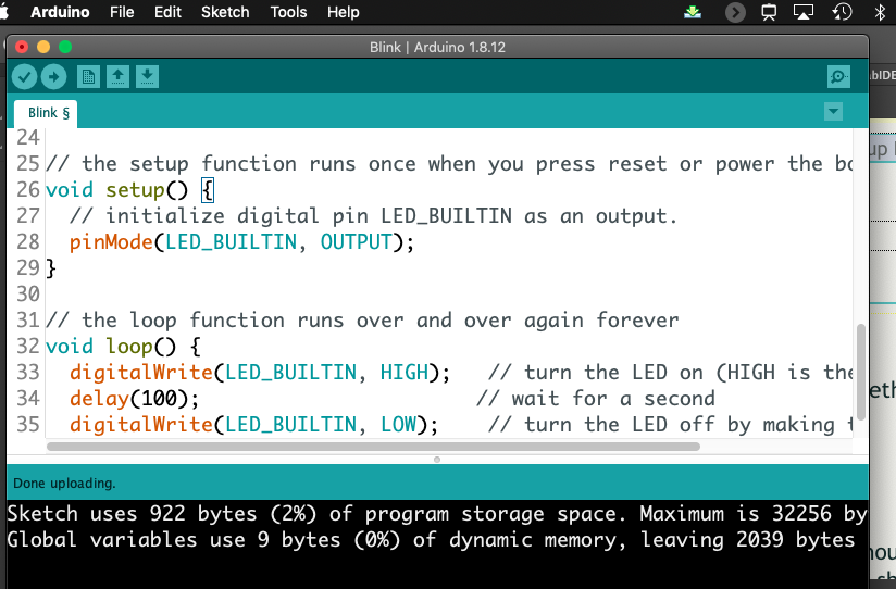
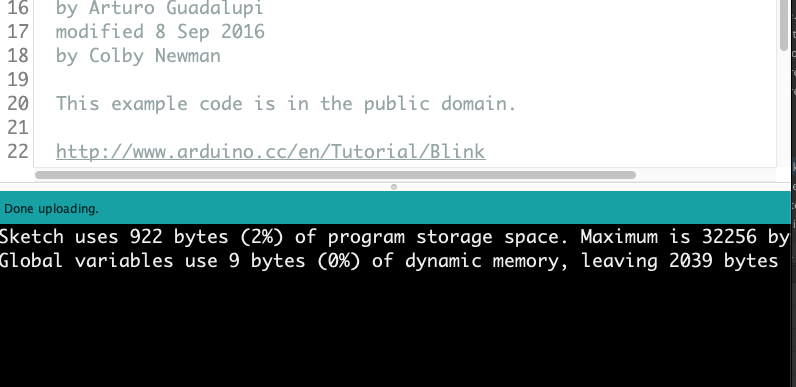
When your upload works your sketch window should look something like this....notice where it says "Done uploading." in the middle of the sketch window.
Step 5:
Once you get the port working there are a couple of other things I want you to notice before we go on. This whole system is not particularly clever and if you tell the IDE to upload the sketch again it will just do that (it won't cheekily point out to you that you just did this!) Upload the sketch again but this time watch the area on your Qbot between the micro USB and the power switch. You should notice 2 blue LEDs flashing there for a few moments. These LED's indicate the back and forth communication between the IDE and the Qbot. You should expect to see those blue LEDs flash every time you upload a sketch. It will look a little like this.
Done!
Now you can return to the lab....
