Dynamics of Angular Motion:
We have a fair amount of experience from our lives about forces that make things rotate. Whether that experience is from pushing on doors in different settings or working on machines or tightening bolts. Like many topics in PH211 what we want to do is put those experiences on a more mathematical basis that hopefully aligns with your actual experiences. Pushing on doors to get them to open or close is a fairly universal experience that we will refer to often in this discussion.
It Still Takes a Force:
Part of what we have to be attentive to is that it still takes a force to make an object rotate. The difference is that the same force applied in different ways will produce more or less angular motion depending on the geometry of how we apply the force.
The Direction of the Force:
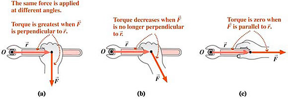
If we consider a door where we are pushing with some specific force on the doorknob we can ask, even though it rarely happens in real life, what the effect of applying that force at different angles would be. The following image is of a crescent wrench but the idea is consistent with applying a force to a doorknob.

The core message here is that when we consider the radial vector from the axis of rotation to the particular point at which the force is applied the forces perpendicular to the radial vector are most effective at making the object rotate. As the angle of the force moves from perpendicular to parallel (aligned) to the radial vector the efectiveness of the force at making the object rotate goes to 0.
Distance from the Axis:
We are also aware of the effect of trying to open a door when, for whatever reason, we need to push on the door very close to the hinge. This happens sometimes when you are trying to open a door for someone carrying a load while staying out of the way. What we are quickly impressed by is the importance of the radial distance from the axis of rotation.
Thinking in Components:
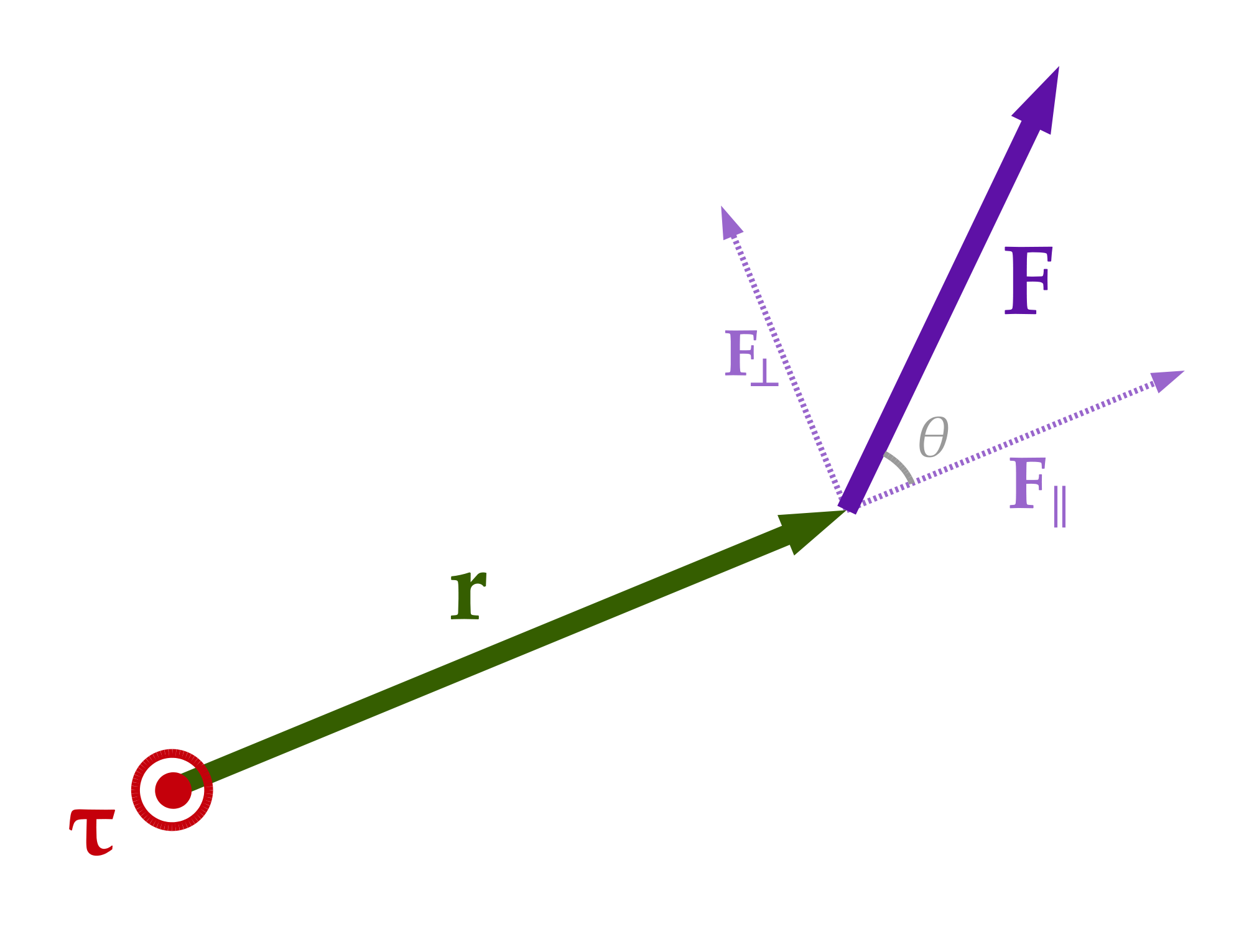
If we create a freebody diagram of a force being applied to an object which might rotate we might end up with something like this.

As always we can reexpress the force in terms of components. In this case it is helpful to take components perpendicular and parallel to the radial vector. This is because the component of the force parallel (F∥) to 'r' does nothing to make the object rotate while the component of the force perpendicular (F⊥) to 'r' is maximally effective.
Torque:
You may notice that any force that has the same perpendicular component F⊥ = F sin(θ) will have the same behavior. Pulling all this together we define the torque (τ) this way.
![]()
In this expresion θ is the angle between the direction of the radial vector and the force vector as labelled in the image above.
Given that both r and F are vectors the math folks are aware that this expression describes a particular form of vector multiplication called the vector cross product. We can rewrite this expression in vector form as...

Given that the torque is a vector it is a reasonable question to ask what is that direction. The short answer is the RHR (Right Hand Rule) and the longer answer involves determinates. I am going to postpone that discussion for now as a potential distraction. I may come back and fill this section in with more detail.
Newton's 2nd Law and Torque:
Returning to the previous image lets imagine that the force is being applied to a mass (m) located at the end of a massless rigid rod (also available from the catalog of ideal physics equipment). If Newton's 2nd Law is valid it must be valid for this setting as well. Because the mass is attached to the end of the magic rod the acceleration must only be in the direction of F⊥ which is tangent to path of the mass because the path is a circle.

Putting this in math terms we get an interesting expression after we take the cross product of the radial vector with the net force....

We can recognize the term on the left as the torque produced by the net force. On the right hand side there are a number of vector relationships that are discusssed in MTH 254 that lead to the following expression. We will not explore those steps in detail here.

The mr2 term is like the mass term in Newton's 2nd Law but captures the idea that both the mass and the distance from the axis of rotation matter when we appy forces to masses which rotate. We identify this as a new concept called the moment of inertia which is usually represented with an 'I' and has units of kg m2. Using this notation we would say, for this specific case of a point mass...
![]()
Physical Objects:
Physical objects are made up of many point masses. Each those bits of the larger object have different radial locations at the very least. This doesn't change the torques due to forces on the object but it does change the moment of inertia. More generally we frame Newton's 2nd Law for rotation as ....

Statics:
In cases where an object is subject to torques but is not moving that implies that a=0 and there is no need to know the moment of inertia. Then the torques due to each of the forces in the freebody diagram must add up to 0. By convention forces which seek to produce counterclockwise (CCW) rotation are positive (+) and those that seek to produce clockwise (CW) rotation are negative (-).
Problem Solving:
Not surprisingly we take almost the same approach to rotational Newton's Laws problems as we did for 'regular' Newton's Laws problems. We start with a freebody diagram. Assuming the object is NOT translating we then determine the torque (τ = r sin(θ) F) produced by each force on our freebody diagram. The sign of those torques is assigned based on the convention noted above. Add them up and set them equal to 0 and you're there. As always we stop and count variables along the way to be sure that we have enough information to solve the problem.
Sample Problem:
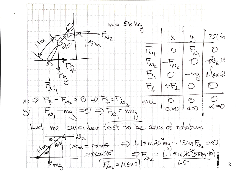
When you (m = 58 kg) put your hands on the wall at shoulder height (h= 1.5 m) and lean into it at an angle of 20˚ with respect to the vertical you need to apply a force to the wall to keep your nose from being distorted. There are three forces acting on you and your center of gravity is 1.1 m from your feet. What force (in N) must you apply to the wall if you wish to remain stationary?

Angular Dynamics
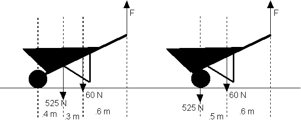
The structure of a wheelbarrow weighs 60 N and there is a 525 N load in the bucket. Two possible designs for the wheelbarrow are shown below. Calculate the vertical lifting force F required in each case.
Angular Dynamics
When you are doing push ups (or in my case trying to) it is interesting to wonder how much of your weight you are actually lifting. Assume your mass is 72 kg, that your hands are 1.5 m from your toes, and that your center of gravity is 1.15 m from your feet. If you are in a horizontal position what force must your hands generate to keep you from crashing into the floor? What fraction of your weight is this?
Assignment: HW: Angular Dynamics
Turn in the various (2) homework problems in this breadcrumb. For these problems please use the problem solving format described in the Concepts breadcrumb.
Assignment: Reading
That's a wrap for this term.... Yay!! See you next term in PH212 perhaps.

