Faraday's Law (or 'How we make electricity!'):
Going back....:
With this idea of flux in hand look at each of the wire loop settings in the previous breadcrumb and think about the flux. Which ones generate current and which ones don't? What is happening to the magnetic flux in each case?
Perhaps it will be apparent to you and perhaps not but if you go back and look the settings that we expect to generate currents are those where the magnetic flux through the loop is changing.
Here's how it is usually formalized as Faraday's Law:
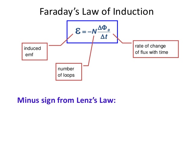
The induced EMF (umpf!) is a voltage which makes current flow. We call the voltage that is produced by this process an EMF (ElectroMotive Force) because it is different from just putting a battery in the loop. This force which moves the charges along the wire is distributed throughout the loop and not just at one location. The script E is used to indicate this effect (which is measured in volts just to be confusing) and distinguish it from the symbol we use for an E field.
In spite of the fact that we are NOT creating little batteries if we have multiple loops of wire connected sequentially to form a coil the EMF in each loop adds to the next as if the batteries were stacked. As a result, stacking 10 loops to make a coil produces 10x the 'voltage' as a single loop. As you will see this is a good thing since the EMF (voltage) produced by single loops is typically tiny.
Lenz's Law is about the minus sign in Faradays' Law which defines the direction the current will flow. We will talk more about this later.
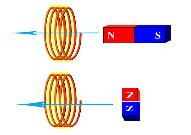
Activity: Consider this setting which allows us to consider a number of thought experiments. In each case determine whether there is a non-zero flux and if that flux is changing?
i: The magnets can be moving toward or away from the coil in each case
ii: Reverse the magnets and repeat your examination
iii: Place the magnet so it is centered in the coil and repeat.
Phet Simuation: The fine folks at the University of Colorado (who brought you Electric Field Hockey) have made a simulation for this experiment as well. Their simulation does NOT give you the option of exploring the effects of turning the magnet 'sideways' which is unfortunate. It does allow you to drag the magnet around in different locations to explore how much 'voltage' is generated in two different coils. If you play with this before class you will know all the answers:)
HW: Faraday
Robots are sometimes designed to follow wires embedded in factory floors. These wires carry steady (DC) currents. The robot carries a coil (many loops) of wire which it holds near the floor and to one side of the wire. As long as no current flows through the coil wire the robot knows that it is following the along the wire embedded in the floor. If the robot turns away from the floor wire a current flows in the coil which notifies the robot of its error. How does this system work? Do I have to say sketch?
Time for Numbers:
You've had enough calculus to know that we can rewrite Faraday's Law this way thinking of the derivative as a ratio of change over a time interval.

Imagine that we make a circular coil (radius 1 cm) out of 10 loops of wire. Then I take a Nd (neodymium) magnet (the kicky refrigerator magnets) which has a B field of about 0.3 T near the surface of the magnet and falls rapidly away to 0.01 T a few cm away. Let's call the average 0.1 T. I place the magnet so one of it's poles is at the surface of the coil 'pointing' through the coil. Then I pull it away from the coil 'as fast as I can'. Let's call that 0.1 s. Now I know, that's a whole lot of soft numbers that I just tossed out there. I think if you check, all of them will turn out to be pretty reasonable. So, how do I figure out how much voltage (EMF) and generate under these circumstances?
That tiny voltage is not going to turn on any lights around here is it. On the other hand, I can turn on an LED with 1.5V or a little less. A little quick math suggests that if I could get a coil with 5000 turns (roughly) I should be able to light up an LED (attached to the ends of the coil). I have such a coil in the stock room and in a f2f class I would hand it around the room and let you play with it. The best I can do here is show you a video (thanks to Joe Reiderer from Wisconsin Rapids Middle School). He shows you how he made the coils and then drops a magnet down the PVC tube. By the end of this breadcrumb you should be able to explain why this is unlikely to work if he uses an aluminum tube. In case you're curious the wire he's using is called magnet wire and can be found in the coils of any old electric motor. It is insulated with a thin coat of varnish to keep the wire thin and not take up too much space. How many turns do you think his coils have? Does this support our previous calculation?
Since LED's only let current flow in one direction (and only turn on when the current flows in that direction) does it matter which end of the magnet goes first down the tube? Think about this and we'll come back to it.
Generators:
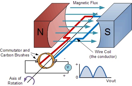
Consider this image. There are many things to consider here but we'll start with the conceptual part. In crude terms the coil moves through 4 quadrants. From horizontal (1) (currently) to vertical (2), back to horizontal (3) and then vertical again (4), and finally back to its original position (1). The sketch indicates the the coil is rotating counterclock wise.
Activity: For each of the 4 'stages' of this process [1 -> 2, 2 -> 3, 3 -> 4, and 4 -> 1] determine whether the flux is increasing or decreasing. Is it changing more rapidly at the begining or the end of that particular cycle (sketch and think!)? Do you think the current will change direction in the next part of the cycle or remain the same? This is a lot of stuff to think about - take it one step at a time and ask for input if you need it.
Now with Calculus:
The magnetic flux is given by the expression ΦB= B . A = B cos(θ) A. A quick examination of this problem suggests that both B and A are constants. The only thing which is changing is θ. As was mentioned in a previous HW problem we can describe θ using angular variable as θ = ω * t where ω is the angular velocity in rad/s.

Applying Faraday's Law in it's calculus form we get EMF = -N d ( B cos(ωt) A )/dt = -NBωA(-sin(ωt)) = NBωAsin(ωt). This represents a varying voltage that has the form of a sine function with a frequency that depends on how fast you spin the 'loop' and an amplitude (maximum voltage) determined by all the physical features of the generator.
Because the frequency of our electric grid is important to many of it's functions the power companies that produce our electric energy are very careful to control the speed at which their generators turn. Once you decide how fast you will let the generators spin then you can design the rest of the system to deliver a specific voltage output.
Does that make you wonder about wind turbines and how that works? A topic for another time and another class.....or a project.
HW: Faraday
The magnetic flux through a loop is given by the expression
.
(the flux is in milliwebers or mT-m2) What is the magnitude of the induced voltage at t=2.0s?
HW: Faraday
Using the previous result [ EMF = NBωAsin(ωt) ], design a coil which will generate a 622 V maximum output when rotated in a field of 0.5 T with ω = 377rad/s (gives us 60 Hz power). There are many solutions to this problem.
Final Thoughts:
Once you know how simple the idea is it's very hard not to want to play and build generators and other devices. Go do it!
These are some great people to know about -- Otherpower.com! Here is a simple but effective wooden alternator that they built. Can you explain how/why it works?
Perhaps this will stay around -- a lovely physics coursepage on generators.
Lenz's Law:
So now it's time to figure out what the Lenz's Law thing is all about. Lenz's Law turns out to be a statement about conservation of energy but let's not get ahead of ourselves. The demonstration that Derek Muller shows in this Veritasium video is one that I usually do in class. See what you think....
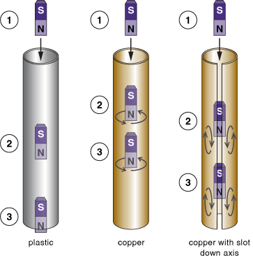
Here is a visualization of the magnet falling down the tube to prep for my video explanation....
Lenz's Law can be summarized in words this way:
The induced current (due to Faraday's Law) flows to oppose the change in flux. If the flux is decreasing through the loop then the current flows to make more B field in the same direction. If the flux is increasing through the loop then the current flows to cancel the increase by making flux (B field) in the opposite direction to the original flux.
Lets apply this to the magnet falling through the conducting tube.....
Activity: Can you explain whether cooling the copper tube with liquid nitrogen will lead to the magnet falling slower or faster through the tube? Why?
Here is a video to give you feedback on your thinking....
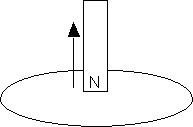
Activity: The north pole of a magnet is moved away from a copper ring as shown. Which direction is the current flowing in the part of the ring furthest from you.
|
|
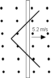
Activity: In the following HW problem which way does the current flow around the triangular loop as it slides to the right?
HW: Faraday
Two straight conducting rails form a right angle and are spanned by a conducting bar. The bar begins at the vertex of the rails and moves at a constant 5.2 m/s to the right. The B field points up out of the page and has a magnitude of 0.35 T. Determine an expression for the flux through the “loop” as a function of time. What is the induced voltage around the loop as a function of time?
|
|
Apocryphal Story of Clever Rancher:
As the story goes a rancher in a remote area had large power lines running through his property parallel to one of his fences. Reasoning that the AC current (I = I0sin(ωt)) in the overhead line would produce a changing horizontal B field where the fence was he saw an opportunity. He hung a coil with many turns on his fence posts which looked pretty much like the fence. From Faraday's Law he knew that if the B field is changing then the flux through the coil was changing and it should generate an EMF (voltage) the could use to provide lights in his remote line shack. According to the story the power company eventually noticed that they were losing power (which is bankable for them) along one stretch of their line and came looking. The rancher was charged with 'stealing' power but it is never clear whether the power company could document how much he owed them.
Activity: This story exists in many forms across the western US. Does it seem plausible? What do you suppose is the impact of the other wires -- usually 3 phase power -- on this scheme?
Here's an engineering paper describing a similar system that is used to monitor powerline performance for your enjoyment.
Finally:
Eddy Current Drag:
Another topic of interest that will have to wait for a future time....
Regenerative Braking:
Modern electric vehicles all use Faraday effects to generate energy to put back into the battery as opposed to using friction brakes to slow the vehicle. I'm not sure of the details so I will need to update this when I find out.
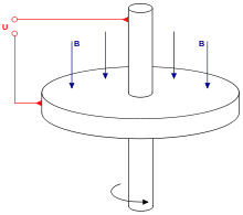
And... a really cool application of Faraday's Law, a homopolar generator... Lots of discussion and other homopolar generators and motors from our friends at the University of New South Wales in Australia (thank you mate!). Faraday also figured this one out more than 150 yrs ago.
Assignment: HW Faraday
Turn in all the problems for HW Faraday in the LMS
Assignment: Reading
Go on to Periodic Motion I breadcrumb to start our discussions about periodic behavior and waves.
Here is an extra video from Penn State illustrating some other interesting effects associated with Faraday's Law. Also gives you a great stereotypical vision of a physicist:)
