For this test it would be helpful to load up your Blink sketch using the internal LED (pin 13 probably) as the LED. This will allow you to see if the sketch is actually executing properly when we power the Arduino externally.
Step 1:
The generic layout of an Arduino is shown below from the Intro to the Arduino Board page.
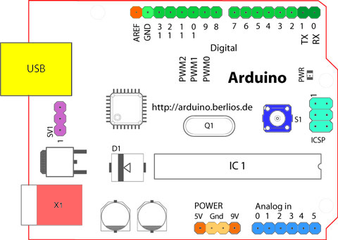
For us the options to provide power are through the barrel jack (X1) or the 9V and Gnd pins along the bottom edge.
Regulated vrs Unregulated: As a digital device the Arduino needs well behaved power that is a steady 5 V with no blips or spikes. A USB power cord connected to a standard USB port is a regulated power supply. That power can be provided to the USB port as we have been doing (top left - yellow in the image) OR it can be connected directly to the 5V and Gnd pins along the bottom edge. DO NOT connect an unregulated power supply to these pins! A battery by itself is not regulated. If we provide battery power to the Arduino we need to provide more than 5 V so that there will still be 5 V of potential after the regulation process uses some energy. The 9V pin accepts unregulated voltages between 6 and 12 V. The internal electronics then manage that input voltage to provide the steady regulated 5V that the Arduino needs.
Competition between Sources: While the Arduino does have so checks to avoid problems from having multiple power sources connected the prudent student will not connect a battery unless the USB port is disconnected!
Step 2: Polarity:
As we are starting to discover in class electric potential (V) has a (+) and (-) side. From an electronics perspective many devices are sensitive to how the power is delivered. In our houses this is less important generally because AC supply voltages alternate between (+) and (-). Our Arduino is a DC device and hence sensitive to which wire is (+) and which is (-).
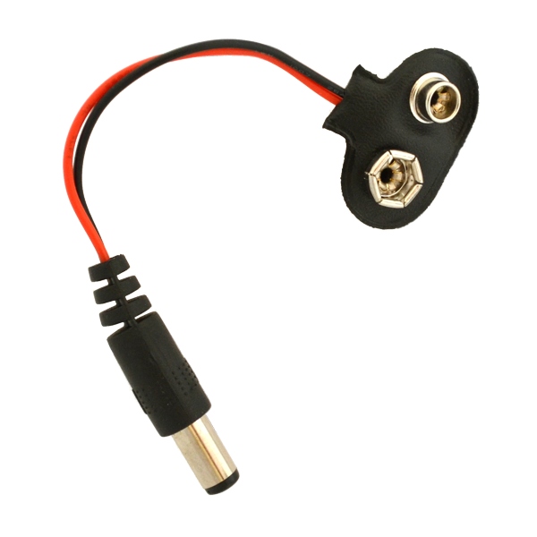
9V Polarity: Check out the image below. The (+) terminal on the battery should be clearly labeled and be the smaller connector (male) on top of the battery.

If you look at the connector (below) that came with your kit it also has matching connectors that assure that the (+) terminal of the battery is connected to the red wire of your connector. While this is generally true it never hurts to check and make sure. I will assume that your connector meets this standard for the remainder of the term.
It is important to note that connectors like the barrel connector illustrated above can have different polarities even though they look the same. Some have the (+) on the inside of the barrel (called the center pin) and others are (-). I bring this up because I have occasionally salvaged a barrel connector from another device and when I hook it up I have to be conscious of these two possibilities. The image below illustrates how this polarity is indicated on a drawing.
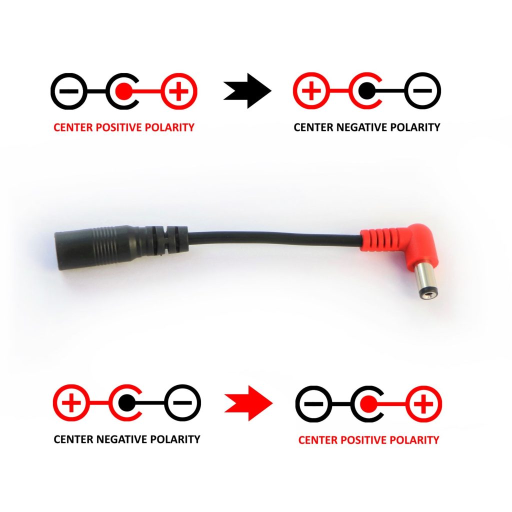
Be aware....
Step 3: Plug it in!
If you have a 9V connector that came with your kit then you can disconnect your Arduino from the computer. Plug your 9V battery connector into the barrel jack and watch your builtin LED flash:) If your 9V connector does NOT have a barrel jack attached then you will need to connect your black wire to the right hand GND pin in the first illustration and the red wire to 9V pin next to it on the on the right. GND pin first and then 'hot' is the standard best practice. Again, when you do so the Blink sketch which you loaded should fire up.
Final Observation:
On every Arduino, and many other digital devices, there is a reset button. This button/switch momentarily interrupts the power which restarts whatever sketch is currently loaded on the Arduino. This is sort of like turning your computer off and then on when it gets totally locked up for some reason. The reset button looks something like this...