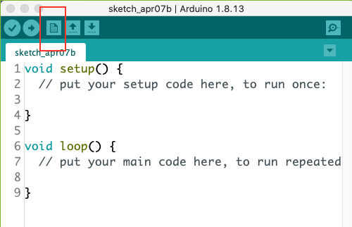
For most of the labs we do I will give you a basic framework for the Arduino code that you need to get started. You will be asked to make modifications to the code and extend it's functionality in various ways. Like working with Jupyter notebooks part of the goal is to learn to just read the code and translate it into conversational english. There are also a number of recommendations for minimizing the risk that you will work on the lab for several hours and then lose your work which will be quite frustrating since I sort of did that just a minute ago.
Step 1:
Just to the right of the upload button at the top of whatever sketch opens when you start up your IDE there is a button which opens a new sketch. Use this to open a blank sketch.

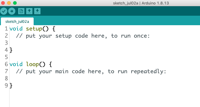
Your blank sketch will look something like this (I know, it the same as the sketch I had showing above). Select and delete all of the code in this blank sketch.

Step 2:
When I give you some code to work with I will try to remember to always embed it in a color block like the one below. Copy all the code (this will be a bit of a pain for long ones) from the first '/*' at the begining to the last '}' at the end and paste it into your empty sketch from the previous step. Immediately afterwards save this sketch with some useful name where you can access it in the future. This code I called MyBlink but you can call it anything you want.
/*
MyBlinkTurns an LED on for one second, then off for one second, repeatedly.
This version of Blink allows the user to make an arbitrary pin to 'blink'
Most Arduinos have an on-board LED you can control. On the UNO, MEGA and ZERO
it is attached to digital pin 13, on MKR1000 on pin 6. LED_BUILTIN is set to
the correct LED pin independent of which board is used.For the purpose of this version of Blink you can choose which pin you wish to
use to 'blink' and LED. To chose a new pin merely change the pin number after
int testPin = 13;
to whatever pin you would like to use. You can change the timing of the blinks
just as you did with the original Blink sketch.
modified 8 May 2014
by Scott Fitzgerald
modified 2 Sep 2016
by Arturo Guadalupi
modified 8 Sep 2016
by Colby Newman
modified 6/15/20
by Bruce Emerson*/
//Define the pin I'm testing with this sketch
int testPin = 13;
// the setup function runs once when you press reset or power the board
void setup() {
// initialize the testPin as an output.pinMode(testPin, OUTPUT);
}// the loop function runs over and over again forever
void loop() {digitalWrite(testPin, HIGH); // turn the LED on (HIGH is the voltage level)
delay(100); // wait for some time in ms
digitalWrite(testPin, LOW); // turn the LED off by making the voltage LOW
delay(1000); // wait for some time in ms// You can turn the pin off and on in more complex patterns to mimic Morse code
// or other patterns of interest by adding more lines after the ones above.
}
Step 3: Save your Blinky Sketch
Save your Blinky sketch somewhere sensible on your computer. You will notice that it saves the sketch inside a folder of the same name.
Step 4: Walk through this Discussion of the structure of an Arduino Sketch
Previously we just made the dang thing jump through hoops and now we need to start having a conceptual understanding of what is happening. Read through the discussion first and then be prepared to come back to it as complete the tasks in the lab.
Step 5:
Confirm that you can make pin 13 (the on board LED) do what you want by making it flash long and then flash short (dash - dot in Morse code).
