More Than One Wave: Same frequency/wavelength on Different Paths
Interference is a generic word to describe the results of superposition of multiple waves at a particular point in space. All of the wave situations we have been exploring are the result of interference. However, it is also true that the word interference is often used to specifically describe the circumstance where we have multiple waves from one or multiple sources arriving at a particular location by different paths. We usually start by exploring two source interference where both speakers or lights are producing waves with the same frequency/wavelength and amplitude.
In sitting down to update this breadcrumb I realize that this particular interference effect, though important, is often pretty subtle from an experiential point of view. Path dependent interference effects are common but often much more complex than the two source model that we traditionally use in physics to introduce the effect. In addition to the physics of path dependent interference this also a setting which extends our problem solving skills in physics in new directions. Much like the emphasis I asked you to place on sketching possible solutions to standing wave patterns I will also emphasize effective sketching as a tool for understanding interference.
Over the years I've tried a number of ways to demonstrate this phenomena with less than compelling success. The demos do work but, as you will see in a later video clip, the effect is not dramatic unless everything is just right.
Idealized Version: PhET Interference
If you start up the linked interactive simulation (the interference version) you will see that you can observe the propagation of waves from two sources through an environment. I find the speaker version a little easier to visualize and I think it make it easier to think about if you run it slow (button near the bottom). There is clearly a pattern established that looks something like this:
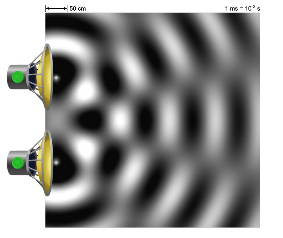
I hope that you see that there is a pattern which seems regular and repetative. This suggests there is a basic explanation for the pattern. To assure you that the patterns you see in the PhET simulation are legit here is a clip (just 60s or so of this clip) of Derek from Veritasium demonstrating this effect on a pond. Notice the agreement between the simulation and the experiment.
Physics Problem Solving: Step 1: SKETCH!
Our first step in physics is always to sketch the physical setting we are exploring. It also helps to be as clear as possible about the specific setting we are seeking to describe. Here is a description:
Two sources of waves (sound or light are possibilities) are located some distance apart from each other and facing in the same direction. Some distance away from the sources (at least several times the separation distance) there is a wall or screen. Both wave sources are in sync meaning that when the crest or trough of a wave is 'emitted' from one source the other is 'emitting' a crest or trough of a wave with the same frequency or wavelength. We are interested in the interference of the two waves at some point on the wall or screen.
Activity: We will take a few minutes for you to start a sketch of this situation and ask questions. Then we will break out into groups to share our work. Explain to each other why you put particular information on your sketch or why you did not. This is an opportunity to learn from each other. In the end evaluate your sketch using the rubric below.
Needs Attention Sketch is drawn but it is |
OK but could improve. Sketch has no incorrect information but has either no or very few labels of given quantities. Subscripts are |
Good Job! Sketch contains all key items with |
Possible Outcomes of Sketching:
Here are some sample sketches we will consider and discuss. Which versions of the sketch do you prefer and why? Does it seem like some of them know something about the result that the rest of us don't?
All of the sample sketches came out of different textbooks. Parts of all of them might be very useful in trying to figure out this problem which is what we are doing. The ones that include the answer are getting ahead of our process.
For our purposes I think that the bottom left sketch is perhaps the most honest and reasonable sketch for you to have made. It would be more clear if it included a midline (like EC in the top left). Given what we've talked about so far it's not clear why any reasonable person would include all the angle labels at this point.
If you are working alone on this it doesn't really matter what symbols you use but for convenience we might consider the following common symbols -- d = distance between sources, L = distance to the 'wall', y = distance from the perpendicular bisector of the line between the speakers -- often called the midline, and P is a point on the wall. r1 and r2 are reasonable labels but they could be L1 and L2 as long as you don't confuse them with the distance to the wall.
Starting Concept:
What you can see from your drawing is that if the waves start out at their respective sources with crests at the same time those crests will not usually arrive at P at the same time. Take a second and be sure you are comfortable with this. Is it clear that what makes the waves from each source arrive at P at different points in their cycle is the difference in the distances each has to travel? For convenience I will refer to this as the 'path difference' going forward.
Clarifying That Idea on Sketch:
Generally everyone's sketch has a short path and a long path. How would you mark the point on the long path that is the same distance from P as the short path? Do you see the isosceles triangle that is formed? Label the portion of the long path that represents the path difference. If you look back at the sample sketches this path difference is labelled 's' in the top left sketch and 'δ' in the top right sketch. (No need for angles yet!)
What If?
Look at your sketch and consider what would happen if the path difference were exactly a full wavelength (1λ) of the wave. Crests from both waves would arrive at P and the same time. Given our understanding of superposition of waves that would give us an extra large crest at P every time crests arrive (extra large troughs as well?). What happens at point P as the waves from each source keep traveling towards P? Do you see that the crests arrive with cress, the troughs with troughs, and every in between point on both waves is doubled? At point P would detect/see a wave or periodic behavior? So many things to think about for such a simple seeming setting.
This form of interference (superposition) where the resulting behavior at the point is greater than either individual wave is called 'constructive interference'.
What if the path difference were 2λ? Same deal? 3λ, 4λ, 5λ,.... see a pattern? How do we write this down?
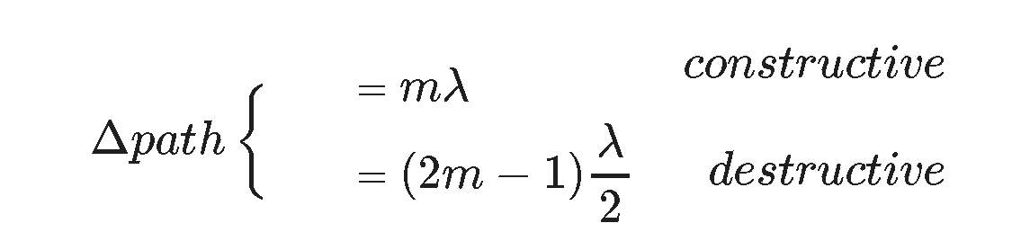
for constructive interference Δpath (path difference) = mλ where m = 1, 2, 3,...
What If Again?
Perhaps you've already thought about what happens if the path difference is 0.5λ? Doesn't that mean the crest from one wave will arrive exactly as the trough from the other wave arrives and vica versa? What about the in between points? What happens then? Haven't we seen this before? Remember like that moment when the two waves in standing waves are travelling through each other and totally cancelling the wave? Very much the same except the cancellation happens all the time!
If we called the previous behavior constructive interference it only makes sense to call this destructive interference.
What if the path difference were 1.5λ (3/2)λ? Same deal? 2.5λ, 3.5λ, 4.5λ,..(5/2, 7/2, 9/2).... see a pattern? How do we write this down?
for destructive interference Δpath (path difference) = (2m-1)λ/2 where m = 1, 2, 3,...
CORE IDEA: Interference is always about the path difference (and possible phase shifts at sources)!!
Notice that where the constructive and destructive interference points are depends on the wavelength/frequency of the wave in question.
What If: Last Time?
What happens if point P is on the midline of the problem? When P is on the midline the paths to P from each source must be the same length and it doesn't matter how close or far from the source you are. What type of interference do you expect when P is on the midline (constructive I hope!)? Notice that this particular constructive interference point is NOT dependent on wavelength/frequency.
Language:
The two cases we have discussed and labelled are extreme cases when the path difference is exactly a whole number of λ OR and odd number of λ/2 leading to perfectly constructive or perfectly destructive interference. Generally when we say constructive or destructive interference we mean this idea of perfectly constructive and destructive. In reality the possible outcomes are much more subtle. If the amplitudes of the two waves aren't exactly the same then perfectly destructive interference can't happen though the superposition of the waves will be much lower amplitude (intensity). If the path difference is 0.8λ then there will be some increase (constructive) in the amplitude of the resulting wave at P but less than when the crests are perfectly aligned.
The point is that constructive and destructive interference, as terms, apply more generally to combinations of waves that lead to increased amplitude or decreased amplitude respectively.
Demo:
This demo comes from a lovely collection of physics demos from Dr. Boyd Edwards at Utah State University. I would use them more except that they tend to start by explaining the answer before doing the demonstration which is at odds with my teaching needs for my classes. If you want the standard classroom version of any demo this guy has them and they are well produced. In this demo there are two speakers playing the same frequency (2 kHz which is a little irritating) and Dr. Edwards takes a microphone and a decibel meter out in front of the speakers to find points where the sound is loud and soft. This clip starts at the point where he is explaining the equipment and the actual demo starts at 2:55. Notice that there truly are points where there is no sound (destructive interference) and they are very localized. I have done this demo in a classroom with students using a single ear to detect the loud and soft locations and it does illustrate the effect nicely if you are careful.
Δpath: Geometry
Now take a look at your drawing. Can you use the pythagorean theorem to determine the two path lengths from L, d, and y? The plus/minus depends on which side of the midline source 1 is.
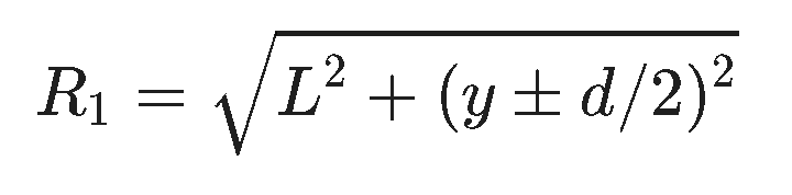
In general this will always work though the algebra can be pretty irritating. What we are usually interested in is y values that correspond to constructive or destructive interference. Because 'y' inside the square root thats what makes the algebra irksome. Shortly we will construct and useful approximation that makes determining constructive and destructive interference points much easier.
HW: Interference
At a concert you sit 12 m directly in front of one of the two speakers on the front of the stage. The other speaker is 8 m from the first. What frequencies in the human hearing range will sound soft to you? (Just get the first two or three!)
Phase Shifts:
An important assumption in our discussion thus far is the assumption that the two speakers (or wave sources) are producing crests and troughs synchronusly. For speakers it turns out to be pretty easy to flip one of the waves by switching the leads on the back of the speaker. This means a trough will leave one speaker when a crest is leaving the other. What happens to points on axis under this circumastance? Do you see that it will produce destructive interference everywhere along the midline? This is a favorite way to aggravate your friends who may be a little overzealous about their acoustic set ups.
Now for a Dose of Reality:
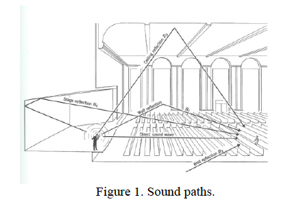
It's rarely as simple as we make it in physics which doesn't mean the physics is wrong but just that reality is usually more complex. If you are listening to a single person in an auditorium that are many paths by which the sounds might arrive at your ear. There are direct paths, there are paths that involve single reflections, and paths that involve multiple reflections or interference between multiple speakers of the sound system. Each of those paths delivers sound of different wavelengths to your ear at different times with different amplitudes and phase relationships.
100 years ago there was no way to actually predict the effect of all those paths due to complexity of keeping track of the many paths and wavelengths for every point in the room. Never mind that there might be multiple performers on the stage. Now we have computers and software that can do all that mathematical dirty work for us. A problem like this would make a great python simulation if we had this material on the table at the begining of the term. It is known that in large concert halls there are particular seats that can't hear certain instruments well in certain groups due to interference effects. In general you are always safe if you sit on the centerline of a symmetric concert hall -- remember that when you're buying tickets!
Extend Your Thinking:
Consider this video. Listen carefully to the intensity of the sound.
Activity: Can you coherently explain conceptually what is happening to each other. Assume the speakers are 10 cm in diameter. How far in front of the speaker is the microphone if the frequency being played is 2500 Hz? You will need to use your sketch thoughtfully to address this question.
Interference of Sound Waves from Two Audio Speakers from ChemEd Xchange on Vimeo.
HW: Interference
You are standing next to a long concrete wall with a speaker. If you place the speaker 10 m away from you and the same distance from the wall you observe that you cannot hear the 68 Hz sound being played. How far are you and the speaker from the wall? HINT: consider the two paths the sound must take to reach you - one is direct and one is reflected. Do you know what the geometry of a reflected wave is?
HW: Interference
Two speakers separated by 80 cm are producing sound at 750 Hz. 4.0 m away a microphone is placed along the centerline between the speakers. Will the microphone detect a loud sound (relatively speaking) or a soft one at this point? How far will you need to move the microphone perpendicular to the centerline until it detects no sound at all (assuming no irritating reflections from walls or observers:)? How much further will you need to move it to find another "loud" spot?
Assignment: HW: Interference
Turn in the various (3) homework problems in this breadcrumb.
Assignment: Reading
Go on to the Interference II breadcrumbs where we will look at a variety of more complex applications of these principles
