Reasonably Far Away:
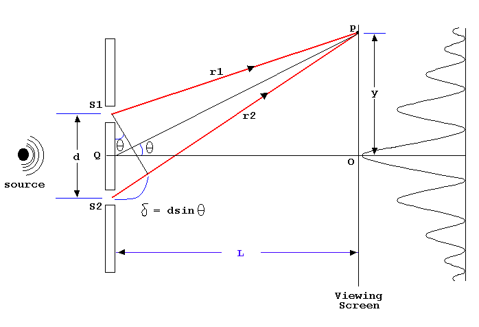
What if L>>d (what does >> mean mathematically?)? Look at your sketch and the geometric path difference. First consider the isosceles triangle we created in our sketch earlier. This allowed us to identify the portion of the path (r2 in this version) that represents Δpath. Where is there an 'almost right triangle' that has the path difference as one of it's sides and d as the hypotenuse? Why is this not exactly a right triangle?

How can you assess when it's reasonable to treat this triangle as if it's a right triangle?
Draw a right triangle and then change the angle in the corner to 85 or 95 degrees so that a new triangle shares the same hypotenuse. How much does this change the length of the 'short side' in percentage terms? Under what circumstances would this be a reasonable approximation? You can see with some rough calculations that if L > 5d then the angles in the isosceles triangle are around 85 degrees and our error is less than 10% from assuming that the triangle containing the Δpath is a true right triangle. For L >> d this approximation is even closer.
I would point out that the geometry that connects the angle θ from the angle describing the direction of point p to the angle in the corner of the 'right triangle' is exact even when we approximate the right angle in the other corner. Once we treat the 'right triangle' as a true right triangle it is clear (hopefully) that Δpath = d sin(θ). In addition, in this drawing, you can see that tan(θ) = y/L. Given that θ is small that means tan(θ) ~ sin(θ). All of which leads to...
Δpath = d sin(θ) = d(y/L) when L >> d
NOTE!!
All we have done is simplify the calculation of the path difference under these circumstances. The basic tool for interference is still the same.

FURTHER NOTE:
This approximation suggests that as the points of constructive and destructive interference get further away from the two sources they will come to depend only on θ which means they should form straight lines through the pattern! This is in fact what we see both in the PhET simulation and in the Veritasium video.
Activity: Back to Derek for a moment. You can see the lines of destructive interference more clearly. Determine the angle of the first destructive interference direstion and calculate the ratio of d to λ for this experiment. Does your result match the data?
HW: Interference Applications
Redo this problem assuming that L>>d (it's not!) and compare your answer to your more exact answer from the previous HW. You will need to figure out θ from the geometry given. At a concert you sit 12 m directly in front of one of the two speakers on the front of the stage. The other speaker is 8 m from the first. What frequencies in the human hearing range will sound soft to you? (Just get the first two or three!)
HW: Interference Applications
Two tweeters (high frequency speakers) are separated by 20 cm. You are sitting at an angle of 15 degrees from the center line of the speakers. When a pure tone (sine wave) is played through the speakers you hear nothing. What is a possible frequency of the tone?
Two Sources Using Light:
We can do this experiment with light though we have to be a little careful about how we get the light to be in phase at the two sources. We can't just use two light bulbs. What we generally do is use a single source of light which is broad enough to fall on two nearby openings (as the sketch at the top shows) which would lead to the crests of the light wave going through both openings at the same time. If we do this with a single color of light (monochromatic light -- single λ) using a laser here is the pattern that we get. To get this pattern the 'screen' is several meters away from the openings and the openings themselves are roughly a mm or so apart.

Image from cnx.org
Generally this makes sense and you can see constructive and destructive interference in the pattern. Given the geometry described for the problem does this meet our expectation for L >> d? (yes) Does the regular spacing of the make sense based on our previous discussion? Consider that
d sin(θ) = d(y/L) = mλ => y = m [λL/d] where m = 1, 2, 3, ...
..which means that y is a consistent and regular interval along the screen. All good!
Can you tell where the central constructive interference point is?
Hmmmm: Practice Noticing!
Does our interference calculation say anything about the brightness of the constructive interference points? Shouldn't they all have 2x the amplitude (brightness) of the original waves? Does that match what we see? (no) Could the diminishing brightness have to do with the increasing distance from the source? Given the geometry described for the problem does this make sense? (no) That's a problem:(
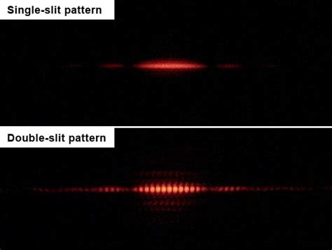
We can see that the constructive interference points are regularly spaced but what happened to the 6th one (and to some extent the 5th and 7th ones) which appears to be missing?
More Information:
Here's a useful bit of information from the same experiment shown above.

(Image: © Creative Commons, Jordgette)
What this tells us is that there are two effects going on simultaneously. Each individual opening creates an intensity pattern that fades away rapidly AND has what appears to be destructive interference points. On top of that is the two opening interference pattern that where an expected constructive interference point is 'crushed' by the destructive interference point of the single opening. The process which creates the pattern for the single opening is called diffraction (also an interference effect).
HW: Interference Applications
Laser light of wavelength 630 nm shines on two narrow openings separated by 1.0 mm. A screen is placed 2 m directly in front of the openings. How far apart are the bright spots on the screen?
Finally:
Go back to the Veritasium video and go to the 3:35 (earlier) in the video where Derek shows what the people seeing in his box. This is a two source experiment using sunlight which has many different wavelengths. Can you explain why, except for the central spot, the colors are separated with red further from the center and blue closer to the center? Look back at our earlier expression for the separation of the spots. Which color must have a LONGER wavelength?(red)
Thin Films:
There are many contexts in which we see vibrant colors that seem related to the colors of the rainbow (individual wavelengths) where there are thin films involved. Here is a classic example.

commons.wikimedia.org/w/index.php?curid=6982732
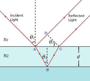
In a perfect universe we would go through the same process of developing a sketch for this setting and eventually figuring an expression that explains what we see. Feel free, for the benefit of your learning, to take a moment to make a sketch of this setting and sort out the geometry. Here is the standard physics community sketch.

If the colors on the soap bubble are an interference effect then there must be at least two waves that make it to the detector (your eye) along different paths. In this case there is light reflected off the front surface of the soap bubble AND off the back surface of the bubble. You have seen this effect in windows where, under the right circumstances, there is a double image. I trust the path difference between the two light waves is apparent?
From geometry you can see that the path difference depends in some complex way on θ1 and θ2 and the thickness of the film - d. We normally simplify this sketch by imagining that the light is coming straight down and being reflected straight back up. In that case the path difference is simply 2d. There is an additional complexity in this case because the wavelength of the light in the film is different than it is in the air. This is because the light slows down in the film (which in this case is water). It is the wavelength in the film that matters. As we will find when we do some optics λfilm = λair/nfilm. This leads to what is called an effective path difference given by Δpath = 2nfilmt where d is usually replace by t for the thickness of the film. What this means is that, for a given thickness of soap film, some colors will be constructively interfered and others will be destructively interfered leading to some complex mixture of all the colors in white light.
This same effect leads to the colors in oil slicks, titanium dioxide coating on jewelry, antireflection coatings on sunglasses and camera optics, and a host of other contexts. We have sidestepped another issue in thin films which are the potential phase shifts in the light produced by each reflection.
HW: Interference Applications
You are exploring a far away beach when you notice that there is a regular erosional pattern on the beach. You estimate that the regions of high erosion are separated by a distance of 40 m. The waves have a wavelength of 15 m and a speed of 2.5 m/s. As you look out into the sea you observe evidence of a reef 500m offshore. Based on this evidence you expect to see openings in the reef separated by what distance?
Three or more sources!
[Bruce wants to do more with this but may not have time!]
With all that you have learned about setting up this problem do a careful and complete sketch of the problem where there are 3 sources of waves instead of just 2. What happens when the path difference between each successive pair (what do I mean by that?) is 1 λ? How would you describe this constructive interference point?
What happens if the path difference between successive pairs of sources is just 0.5 λ? Is this a destructive interference point as it was with the 2 source problem? Is this point as bright as the constructive interference point you identified in the previous paragraph?
HyperPhysics has a great page that shows the intensity patterns for 1, 2, 3, and 4 sources so you can see the relationships. Notice that even a single opening creates an unexpected interference pattern which is superimposed on all of the other multiple source results. We will come back and talk about the single source problem later. You should wonder how you would sketch that problem in a way that would lead to interference effects. For those who just can't wait here's a description of the single source problem (section 14.5 but notice what's in the rest of the document!).
Here's is a lovely example of a multiple source system (12 speakers) and a project to control the phase of each speaker to steer the central constructive interference point around the room.
Assignment: HW: Interference Applications
Turn in the various (4) homework problems in this breadcrumb.
Assignment: Reading
Go on to the Light breadcrumb where we dig more deeply into the nature of light and some of it's unexpected behaviors
