Optics: The interaction of light with materials.
At the outset I would ask you to be conscious that many, if not all, of the effects we will be exploring with visible light also apply to other waves as they pass through different materials.
Plane Waves/Spherical Waves:
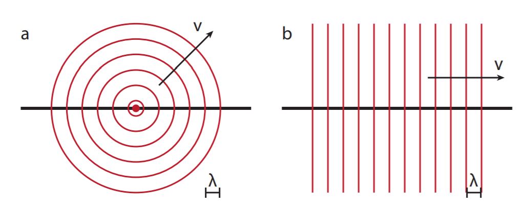
Lets return for a moment to this visualization of plane waves of light. This is what we mean by 'planar waves' and the 'crests' of the waves are the wavefronts.

Image from BMS on physics.stackexchange
Planar waves usually start out as spherical waves that look 'flat' as we get far enough away from the source. Consider this animated gif which is only a slice through a set of spherical sound waves....
Imagine that as you get further and further away from the source the radius of the spherical wavefront becomes large and begins to look flat (planar) for the same reasons that the surface of the earth looks flat to us as humans. Some waves, like ocean waves, have parallel crests because of the way they form but most waves start out a spherical and transition to being planar.
Rays:
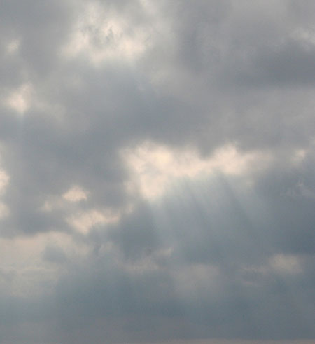
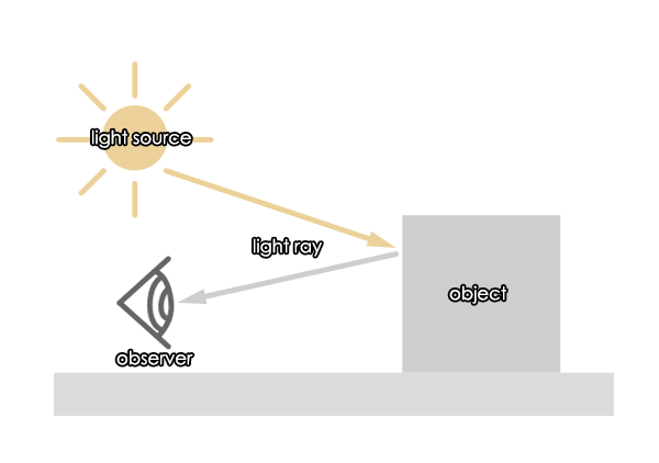
Rays (light rays or sound rays) are an alternative representation of the waves. The 'ray' points in the direction the wave is moving (like v in the image above) which is perpendicular to wavefront. The ray feels a little like a 'beam' of light but it is generally a representation of plane waves rather than a beam. The image below shows what we call 'ray's of light' are a physical manifestation of the idea of rays. The light is a spherical wave originating at the sun which is very nearly a plane wave as it arrives at the earth.
Reflection of Waves:
We can think about the reflection of plane waves from either a wavefront representation OR a ray representation. To understand why waves reflect from flat surfaces as they do it is helpful to consider how a particle 'reflects' off a wall. Since light at least is both a wave and a particle this is a reasonable approach. Consider this image of a ball bouncing elastically off a rigid wall.

Because the colllision is assumed to be elastic and the wall is stationary after the collision that means the velocity of the ball must be the same before and after. The momentum is conserved as long as there are no unbalanced external forces -- important to remember! In the y direction, assuming no friction, there is no force therefore vy is unchanged. If vy is unchanged and v is unchanged that means the magnitude of vx is unchanged. Be careful, the momentum in the x direction DOES CHANGE because the ball has been smacked by the wall in the x direction! The only way all of those statements can be true is if θi = θf . In the mechanical case we think of θi and the initial angle and θf as the final angle. In optics we think of them as the incident angle and the reflected angle.
If we represent this same experiment with wavefronts and rays it looks like this. It can help, though it is not really correct, to think of the wavefront as a collection of little marbles all moving in the same direction.
Just to be difficult:
In MTH254 (Vector Calc) you will find that we mathematically define the orientation of a plane (flat reflecting surface) using a vector called the normal. As you will remember from PH211 the normal force is a force in the direction 'normal', i.e. perpendicular, to the surface. In MTH 254 and optics the normal is a vector or line perpendicular to the surface. Because of it's mathematical importance we measure the angles of incidence and reflection relative to the normal rather than the plane of the reflecting surface as illustrated below.

Law of Reflection:
All of that discussion so we can say:
θincident = θreflected
Application:
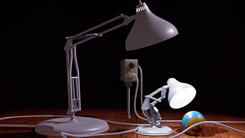
While it seems like a lot of ado about nothing, the ability to define the shape of surfaces using the mathematics of normal vectors and to determine the path of light from a source reflecting off a surface towards a viewer is what allowed Pixar to amaze us with it's first efforts. Doing the math for each pixel of the image is a calculationally intensive process which took many hours of processing time for each frame of the movie. Pixar now has one of the worlds largest supercomputers to do this work. Much of the actual work is still using the Law of Reflection applied to light sources and geometric shapes defined in math.
HW: Optics
You are 1.6 m tall and need to hang a mirror on the wall so that you can see yourself from head to toe. How tall does the mirror need to be and where do you need to stand to see yourself from head to toe? (Law of Reflection) You may find this useful in some future argument about how tall a mirror must be to be able to see yourself from head to toe.
HW: Optics
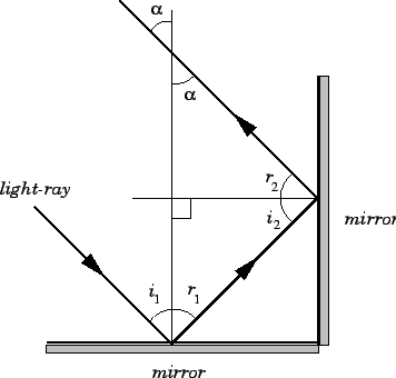
Imagine two (2) flat mirrors at perpendicular to one another (like a corner in a room) and both perpendicular to the floor. Show that light traveling parallel to the floor is reflected around the corner and returns travelling parallel to it's original direction.
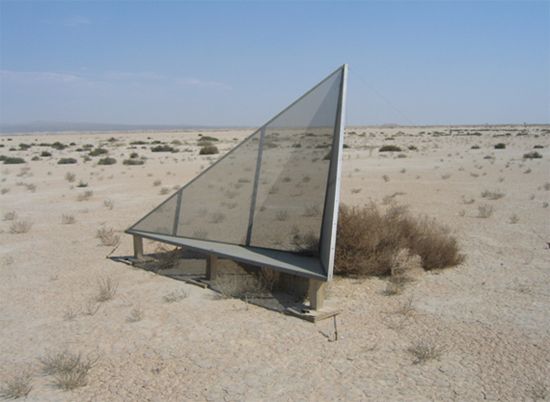
Here is a 3D version of this problem called a corner reflector. It sends waves back exactly parallel to their original path in 3D.
Diffuse vrs Specular:
The rule for reflection applies to any smooth flat surface - like a mirror. This sort of reflection is called specular (from speculum for mirror). What about rough surfaces? In some sense rough surfaces are a collection of little tiny flat surfaces at a lot of different random angles. If you try to figure out the reflection off of all of those many little surfaces you get what is called diffuse reflection. The important difference between diffuse and specular reflection is that diffuse reflection sends light outward in all directions while specular reflection only sends the incoming light in one direction. The reason you can see everyone in a room is because we are mostly diffuse reflecting surfaces which send light all directions. You would be correct that the amount of light going in different directions for diffuse scattering (reflection) is NOT uniform but that is a subject for a different day.
Every point on an object is sending light in many directions. Hmmmm...
How do you see the whole thing? What about each point on the object?
The Chicago Bean is a curved specular surface which leads to lots of interesting experiences if you are ever there. (It's quite cool!)

Moving into a New Medium:
Reflection is simpler partly because the wave stays in the same medium so it's wavelength and speed do not change. When a wave moves across the boundary between two media we call it transmission. Because the medium changes the wave speed and the wavelength change though the frequency DOES NOT! Our eyes detect frequency so this explains why red objects look red underwater as well as in the air.
Index of Refraction:
Because the change in the speed of the affects the trajectory of the transmitted wave we describe the speed of the wave in each medium with the index of refraction. The index of refraction is traditionally labelled n (which is why I used m = 1,2,3... for the counter in standing waves). The index of refraction is defined to be:
n = c (speed of light in vacuum)/v wave in the medium = c/v w
Because light can never travel faster than c the index of refraction is always >= 1.0. Here is a table of the indices of refraction for a range of materials.
Some indices of refraction you should have a sense of are:
n air = 1.0 - basically the same as a vacuum unless you have a very precise setting.
n water = 1.33 = 4/3 - yes, it depends on contaminants etc etc but this is a good number
n glass = 1.4 - 1.7 - for typical glasses and about the same for optical plastics
n diamond = 2.4
Refraction:
Imagine that there is a wave (series of 'crests and troughs') that is traveling through some medium. This wave is a plane wave which is rather like a 2 dimensional version of an ocean wave. Now imagine that this wave encounters a change in the medium through which it is propagating. In this new medium the wave will move slower than it was. The boundary of this new medium is at an angle to the direction the wave is going. Here is a sketch of what that might look like.
Because the lower edge of the incoming wavefront reaches the slower medium first the wavefront has to turn (bend) to stay connected. This is actually actually a lovely demonstration to do with students lined up like a band on the commons (note to future teachers). Can you see that the same change in propagation direction would happen if the wave were traveling from medium 2 to medium one?
Perhaps you can see that there would be no bending of the wavefronts at all if the wavefront was coming straight down with an angle of incidence of 0 relative to the normal. In addition you may perceive that the amount of bending seems to increase as the angle of incidence gets greater.
Conceptual Understanding:
What is good to notice is that if the wave slows down in the new medium it bends TOWARDS the normal and if it speeds up in the new medium it bends AWAY from the normal.
In terms of the index of refraction if the index increases in the new medium it bends TOWARDS the normal and if the index decreases in the new medium it bends AWAY from the normal.
This is useful to remember.
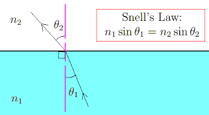
Snell's Law:
The specific relationship between the angle of incidence and the angle of refraction is not particularly clear. Here is what the plotted data looks like for a particular case. Not linear except when the angles are small.
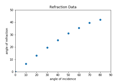
Can you hazard a guess at the relationship? Strikes me as pretty unclear. Here's what we (science folks) eventually figured out.
From our previous exploration can you say which medium has the faster wave speed?
HW: Optics
Consider a coin in the bottom of a bucket whose depth is d. Show that your eyes perceive the light to be coming from a point d*= d/n below the surface of the water. Consider the paths of light leaving a point in the center of the coin. Then use geometry to show that they appear to originate at a depth d*. This is why coins in a water fountain appear closer to the surface then they are.
[Look at where the exiting rays intersect under the surface of the liquid. This is the apparent depth of the coin.]
Assignment: HW: Optics
Turn in the various (3) homework problems in this breadcrumb.
Assignment: Reading
Go on to the Optics Applications breadcrumbs where we will look at a variety of more complex applications of these principles
