Optics II: Applications of the Basic Rules
Its tempting to say-- just apply the basic rules for reflection and refraction to any surface and it's done. While that's a true statement it is much more easily said than done. In the past we developed a lot of sketching tools for estimating what happens in different settings but the reality of our modern world is that optics is done using software programs. There is even a python library for ray tracing
Ray Tracing:
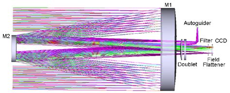
The standard approach to optics is called ray tracing. This is the process of taking a ray of light from an object (which represents a plane wave) and following it through an optical system to see where it goes. Along the way the effect of each optical surface, whether reflective or refractive, is calculated. In the end you can determine what happens with the light.
Not surprisingly there is even a couple of python libraries to facilitate ray tracing. Here are some simple examples of what it can do. The math is relatively simple and the geometry is more complex but that's what code is particularly good at.
Another example....
Language:
Object:
The object in an optical system is the 'object' which is directing light towards the optical system. If the object is far away all of the light from the object is traveling parallel as it gets to the optical system. Telescopes are an example of this. For nearer objects each point on the object is scattering light in many directions from that point towards the optical system. In standard physics representations like the ones below we only show a few 'special' rays from one point on the object. The conceptual vision I would want you to have is that every point on the silly pencil is reflecting light (diffuse reflection) in every direction towards the mirror or the lens. It is relevant to note that the many 'rays' of light between 1, 2, and 3 must stay between them so they will all gather at the same point defined by the special 3 but it is misleading.
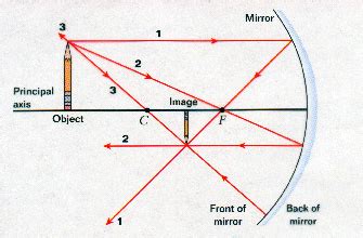

Image:
Someplace in each optical system there is an observer looking at the light 'after' the optical system has manipulated it. In the case of the mirror the observer will be off to the left and in the lens case the observer is off to the right. In each case the observer will perceive the light to be coming from the location that the light has gathered after passing through the optical system. In both cases the observer would see a smaller upside down version of the object. This apparent source of the light that the observer sees is called the image. Images can be inverted or right side up relative to the object as well as bigger or smaller. In both of the cases pictured the light is actually gathering at the location of the image which means you could put a screen at that location and see the image on the screen. In the case of the mirror you have to be careful how you do this or you'll block in light coming from the object.
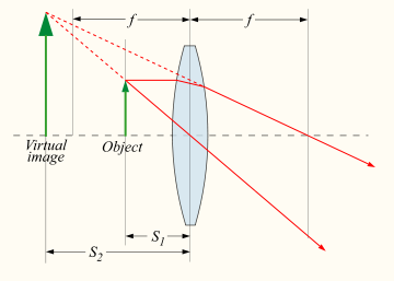
In the case illustrated below the object is the arrow closer to the lens. The observer is off to the right side of the lens. In this case the light is diverging after it passes through the lens and the observer would 'see' the light as coming from the bigger arrow (the image) further behind the lens. This is how simple magnifying glasses work (Sherlock Holmes style). This image can NOT be captured on a screen because the light doesn't actually gather at that point. This type of image is called a 'virtual image' and the previous type of image is called a 'real image'. They are both real in the sense that we can see them.
Focal Point:
For many optical systems (lenses and mirrors) there is a location that will gather all the light from a distant source in a single location. This is called the focal point. Here is a quick example from two types of lenses.

Exploration:
Because we have access to a range of computational tools that didn't exist just a few years ago the value in manual ray tracing seems to me to be diminished. Here is a web based tool that you can use to explore how ray tracing can show us what will happen in a range of simplified optical systems.
HW: Optics: Ray Tracing
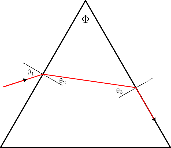
A right prism is a columnar piece of glass whose cross section is a equilateral (actually isoceles) right triangle. Light enters the prism at an angle θ 1 as shown and exits the second surface at an angle of 90 degrees. What is the maximum possible value of the index of refraction of the glass in terms of the angle θ? What happens if n is greater than this value? Be aware that this graphic shows a prism which is NOT a right triangle. In our problem the apex angle at the top is 90o .
HW: Optics: Ray Tracing
Imagine a sphere of glass of index 1.5. Draw a line perpendicular to some point of that sphere (which looks like a circle in cross section). Extend this line inwards until it reaches the center of the sphere. This is the optic axis of the sphere (similar to the previous problem) Consider the behavior of light which is travelling parallel to this optic axis towards the sphere and hits it at some distance d from the axis. Where, relative to the center of the sphere will the light cross the optic axis?
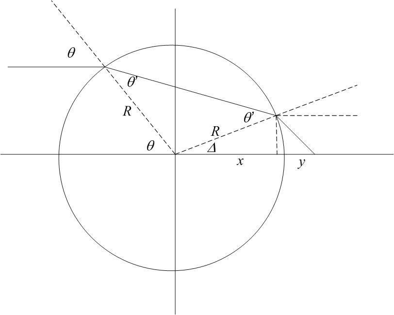
Assignment: HW: Optics: Ray Tracing
Pick one (1) of the two problems above for your homework problem in this breadcrumb.
Assignment: Reading
We are done!! No future reading at this point.
