Polarization:
Before we get specifically to polarization lets explore how one might get the E field to 'wave'. This animation gives a sense of why a moving charge leads to both a changing E field (a ripple in the E field line) and a B field because a moving charge is a current and current's create B fields. Notice that the direction of the ripple in the E field (the red line) is in the direction of the periodic motion of the charge. The green line is the B field from the changing 'current'.
This actual process of moving charges up and down in a vertical line is how we make radio waves and other EM waves. It was a bit of a puzzlement to early researchers thinking about the electrons moving around the atom which also oscillate back and forth. The expectation was that the electrons would create EM waves (light) that would carry energy away and cause the electron to slow down and the atom to collapse. This is not observed to happen so we eventually explained the problem away by saying that when the electrons were in their special orbitals they didn't generate light (magic!) for some reason. For our purposes what's important is that each light wave (or perhaps more properly each particle like thingy with wavey characteristics) has a specific direction in which the Electric Field is waving. As you saw in the previous discussion this direction defines a plane called the plane of polarization.
Polarized, Unpolarized, Randomly Polarized:
A radio wave is the result of chasing electrons up and down an antenna and that wave is polarized. It has a well defined direction that the E field is osciallating. If you had a number of antennas each oriented in a different direction to collective superposition of those waves would have some combination of E fields of all the parts and would be unlikely to have a will defined polarization. When we heat up atoms of a material, whether that is a filament or the Hg vapor in a flourescent light each atom emits particles of light with different planes of polarization since each atom and it's electrons are moving in different random directions. You would not be surprised that we label this randomly polarized light. I would love to offer you a video of this idea but all the videos I find skip past this idea even though it's embedded in what they are talking about.
Most light that we see is randomly polarized. The light that comes from the sun is emitted by many 'atoms' oscillating in many directions so it is a superposition of many polarizations. So is the light from a regular light bulb or a flourescent bulb. The light from LED's is a more complex mix of light which is mostly randomly polarized and some light that is polarized. Because of the process that creates lasers most laser pointers are largely, though not completely, polarized.
Since light is an EM wave it must be polarized since the E field must be oscillating in some direction. When we say 'unpolarized' we actually mean randomly polarized. The only unpolarized light is light that has NO E field which means it isn't really light.
How to Represent Polarization:
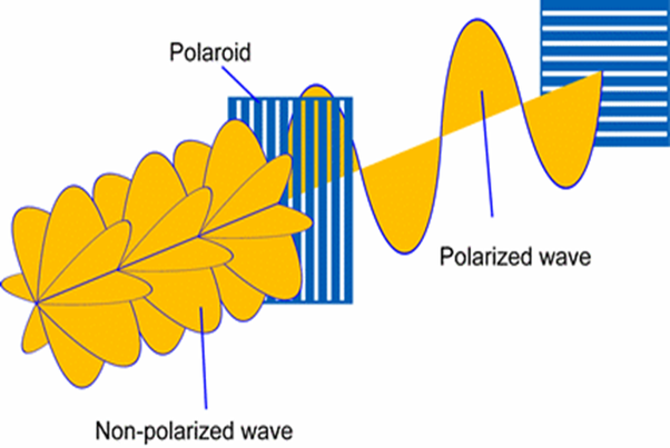
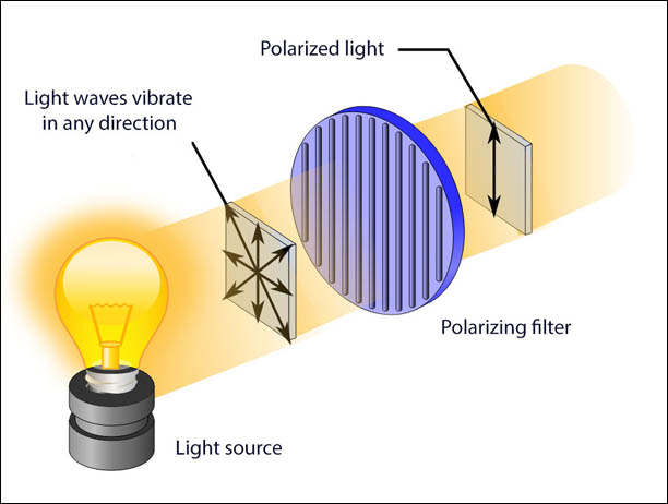
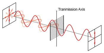
Consider this representation of randomly polarized light and polarized light (don't worry about how the polarizer works just yet). The sketch is illustrating the plane of the oscillation of the E field and is ignoring the B field to minimize confusion.
This is tough to sketch in a problem so here is how we usually represent the same problem in physics classes.....
What is a Polarizer?
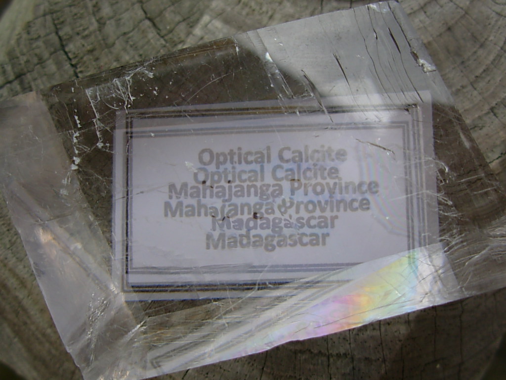
Some minerals are natural polarizers meaning that randomly polarized light passing through them is 'filtered' to produce polarized light. This turns out to be a consequence of the details of their crystal structure and chemistry. Calcite is one of these materials that was used for years in making scientific instruments that relied on polarization. Here is an image of piece of optical grade calcite (much of which was an export from Iceland) showing the birefringence effect (two images). Each image has a different plane of polarization.
When we learned how to make polarizing materials we were able to develop them for use in many modern applications like LCD screens. Edwin Land was one of the first to apply this technology to a host of consumer products developed by the Polaroid Corporation which no longer exists in it's original form. Here is an important/amusing story about the roots of modern polarizing materials (from the wiki page for Herapathite).
Herapathite, or iodoquinine sulfate, is a chemical compound whose crystals are dichroic and thus can be used for polarizing light. The composition of herapathite has been shown by the Danish chemist Sophus Mads Jørgensen in 1877 and others to be 4QH2·3SO4·2I3·6H2O, where Q denotes the quinine molecule C20H24N2O2. The crystal can give up at least some of its water without losing its form and optical properties.
According to Edwin H. Land, it was discovered in 1852 by William Bird Herapath, a Bristol surgeon and chemist. One of his pupils found that adding iodine to the urine of a dog that had been fed quinine produced unusual green crystals. Herapath noticed while studying the crystals under a microscope that they appeared to polarize light.
In the 1930s, Prof. Ferdinand Bernauer invented a process to grow single herapathite crystals large enough to be sandwiched between two sheets of glass to create a polarizing filter; these were sold under the Bernotar name by Carl Zeiss. Herapathite can be formed by precipitation by dissolving quinine sulphate in acetic acid and adding iodine tincture.
Herapathite's dichroic properties came to the attention of Sir David Brewster, and were later used by Land in 1929 to construct the first type of Polaroid sheet polarizer. He did this by embedding herapathite crystals in a polymer instead of growing a single large crystal.
The crystals of herapathite form molecular wires along which electrons can move if pushed by an E field. If a bed of such crystals is embedded in plastic it forms a grid of conducting wires that we can conceptually represent like this..
This is a chance to tie together some ideas from PH212 and PH211. Since the grid of wires is arranged vertically then when the electric field of the incoming light is aligned with the vertical axis it will produce a force (F = qE - PH212) that pushes electrons along the wires (a force applied over a distance moves energy from the E field to the charge). Because the wires have resistance this will take energy from the vertical E field (energy bar charts - PH211) and reduce it's amplitude (making that portion of the light dimmer). Light which has a horizontal E field pushes on the electrons in the wires but because there is no movement of the charge in that direction (think about why normal forces rarely add or remove energy from objects (PH211) no energy is removed from the horizontal E field and that light passes through the grid undiminished. Reread this section until it is clear to you why this is reasonable given all of the physics you know. This is a very nice integration of many concepts we have studied and the thinking it represents is more valuable than the answers you will calculate shortly.
Now consider this representation of randomly polarized light passing through a grid of 'wires'. In an ideal polarizer only the light polarized perpendicular to the wires will pass through and all other polarizations will be gone.
We label the axis of the polarization of the light is PASSES THROUGH the polarizer the transmission axis (TA). Note that the transmission axis is perpendicular to the 'wires' in the polarizing material.
I would note that for longer wavelength light waves one can actually use objects like a barbeque grill to polarize the light.
Take Home:
For light passing through an ideal polarizer:
Light which is polarized parallel to the transmission axis passes through undiminished.
Light which is polarized perpendicular to the transmission axis is (ideally) completely eliminated.
Malus's Law:
But what if the plane of polarization of the light is neither parallel or perpendicular to the transmission axis. You will not be surprised that we consider the components of the E field parallel and perpendicular to the transmission axis.
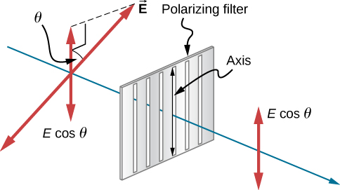
Notice that θ is the angle between the plane of polarization of the light and the transmission axis of the polarizing material. When θ = π/2 no E field gets through (cos(π/2) = 0) and when θ = 0 all of the E field gets through (cos(0) = 1). Now it just slightly more complicated because the intensity of the light actually depends on the square of the E field which means:
Iout = Iincos2(θ)
Iout is polarized in direction of TA
This is Malus' Law which applies only to the passage of polarized light through a polarizer.
Randomly Polarized Light and Polarizers:
For randomly polarized light we have to integrate Malus' Law for all possible polarizations of the incoming light which leads to the following result:
Iout = (1/2) Iin
Iout is polarized in direction of TA
Applications:
Lucky for me this guy, Michel van Biezen, has done a good job of presenting the standard approaches to solving polarization problems.
This first video lays out the basic interaction between polarized light and a polarizing material that we have discussed above.
It is very important to note that the light exiting the polarizer is now polarized in a plane that aligns with the transmission axis of the polarizer. The transmission axis is what Michel is indicating with his lines on the polarizer. Those lines ARE NOT the grid of wires!
In this next clip he explores the effect of two polarizers on the intensity of randomly polarized light which passes through both. He is not wrong but I would like you to reframe a couple of things that he says. The impact of a polarizer on already polarized light depends on the angle between the plane of polarization of the light and the transmission axis of the previous polarizer. That is the angle that is used in the transmission equation Iout = Iin (cos(θ))2. As mentioned before the cos(θ) is squared because the intensity of the light is related to energy which is proportional to the square of the E field.
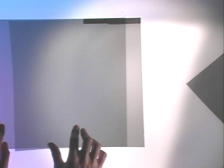
Here some images (thanks to Montana State University for creating these images) which illustrate the basic effects of two polarizers. The first polarizer is nearly always used to take randomly polarized light and convert it to polarized light (with a 50% loss of intensity). The second polarizer is sometime referred to as the analyzer but I prefer to think of it as just another If the transmission axis of the second polarizer is aligned with the plane of the polarization all of the light, ideally, should pass through. Real polarizers have some tint which reduces the intensity a little.
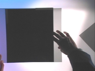
If the transmission axis of the second polarizer is perpendicular to the plane of the polarization none of the light, ideally, should pass through. This orientation is often called crossed polarizers. Again, if you have a bright light, some light actually gets through crossed polarizers.
Here is a short video that also illustrates this effect as well as the in between states. The last example in this video applies to the next setting so remember it as you are looking at Michel's next explanation.
You may notice, if you have polarizing sunglasses, that you can't read the LCD screen of a calculator or phone with your glasses on. This is an indication that the light from the screen is polarized and the transmission axis of the glasses is 'killing' the light from the screen. In another application the Redmond Technology Center building on the Redmond COCC campus has windows that have electronically controllable polarizers embedded in the windows. When the sun is bright the transmission axis of one polarizer is electronically rotated to block the sunlight coming through the window to keep the building cooler. This is different than the photogray material of some glasses.
HW: Polarization
While calibrating a laser the technician places a polarizer, transmission axis vertical, in the beam she observes that the intensity of the light is reduced by half. What are the possible polarizations of the initial laser light (two possibilities!)?
Now move on to this example of multiple polarizers...
Consider how his calculation would be different if the transmission axis of the second polarizer were only rotated 30 degree relative to the first one. I strongly recommend that you sketch the plane of polarization of the light exiting from each polarizer to help develop you understanding. This is why we sometimes say that polarizers 'rotate' the plane of polarization at some cost to the intensity.
Revisit the last 30 seconds of the earlier video and be sure you can explain the effect you see with a third polarizer between the crossed polarizers.
HW: Polarization
Unpolarized (randomly polarized) light passes through 3 polarizers. The first has a transmission axis which is oriented horizontally. Each succeeding polarizer is rotated 30 degrees with respect to the preceding one. What is the intensity and plane of polarization of the light which exits the third polarizer?
This last example gives us a taste of what might happen if we approach a calculus problem where we have a 'large number' of polarizers with very small changes in the orientation of the transmission axis. Hope you find it intriguing.
HW: Polarization
We want the plane of polarization of the light exiting from our equipment to be horizontal. The light entering our equipment will be polarized vertically. What is the minimum number of polarizers needed inside the equipment to accomplish this? What is the minimum number of sheets required if the intensity of the transmitted light is more than 60% of the incoming light?
HW: Polarization
A beam of partially polarized light consists of a mixture of polarized light and unpolarized light. Suppose you view such light through a single polarizer which you rotate through 360 degrees while recording the intensity of the trasnmitted light. You observe that at its brightest the transmitted light is 5 times as bright as at its dimmest. What percentage of the beam is polarized light?
This site can take us to really interesting places that are beyond the central scope of this class. Here is the possible motivation. This is an image of a plastic protractor placed between two crossed polarizers. The change in the colors is most pronounced where the stresses in the plastic are higher. Engineers use this to identify stress points in structures using plastic models of the structure (can't do this with an actual steel beam).

To make sense of this we need to understand that combining two linearly polarized bundles of light can lead to either linearly polarized light OR circularly polarized light depending on the phase shift. The superposition of two circularly polarized bundles can lead to linearly polarized light. The stressed plastic affects the different circularly polarized components of the light differently leading to rotation of the plane of polarization of the light that is stress and wavelength dependent. This is what causes the colors.
Lastly....Checking Those Polaroid Glasses!
Light can become polarized in a number of ways. Passing through a polarizer is one of them. Being produced by a source with a definite polarization like a radio antenna is another. A third way to polarize light is by reflecting it off a smooth surface. Light whose plane of polarization is parallel to the surface it is reflecting off will be transmitted while light whose plane of polarization is perpendicular to the surface is attenuated (reduced). This means that light reflecting off a road way or a lake is at least partially polarized parallel (horizontal) to the reflecting surface. If we put a polarizer in front of that reflected light whose transmission axis is vertical then the reflected light (glare) is blocked. This means the transmission axis of the lenses in polaroid glasses should be perfectly vertical. You can test this by looking at a reflection off a counter (while wearing the glasses!) and rotating your head slightly off vertical each way. If the lenses are properly installed the glare will be minimized when your head is straight up and down. I have found some glasses where I have to turn my head 10 or 15 degrees off vertical to minimize the glare. Not good.
Assignment: HW: Polarization
Turn in the various (4) homework problems in this breadcrumb.
Assignment: Reading
Go on to the Optics breadcrumbs where we will develop some fundamental ideas about how we can describe the behavior of light as it interacts with objects like lenses and mirrors.
