Soldering School: Activities and Notes
The Goal: Here's a view of the completed flashlight project
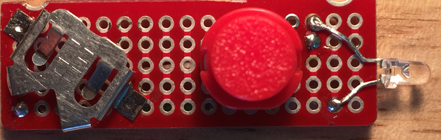
Here's our starting point -- the breadboard
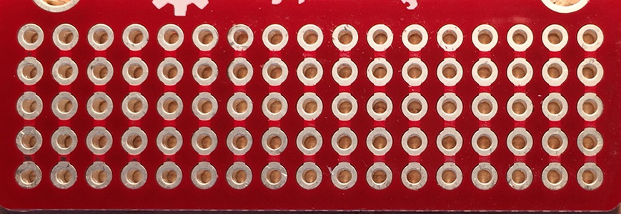
We need to talk about this board because the rows of 5 holes are connected together internally. Between vertical rows of 5 there is no connection. This can be helpful or not depending on the circumstances. In this case the goal was to reduce costs so this is what we got. It's half of a SparkFun miniproject board.
Collins Soldering Video: Thanks to Adafruit!
First wires: From the back
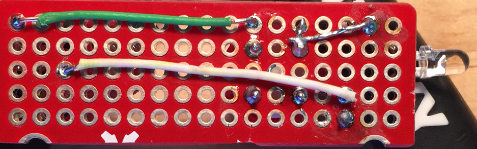
The first items to be soldered are the wires that will eventually connect the battery to the LED light. Note where they start and end on what we will call the back side of the board. Leave plenty of exposed copper on the ends of the wires (we will clip it off after we solder them on). The current that is being carried by these wires is small so we are using telephone wire which is cheap and easy and solid core. The hardest part will be stripping the insulation off such small wires with our big tools. Insert both ends of a wire through the holes and solder from the 'front' side. Do each wire separately and inspect for the features of quality solder joints. Clip the left over copper off short EXCEPT for the left end of the white wire in the image above.
Be sure the wire (the white one in the image) on the left end is bent over flat on the front side. This will form the negative contact with the battery.
Battery Clip:
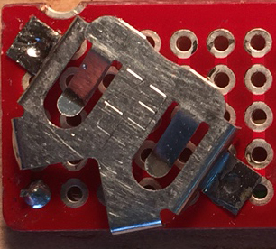
The battery clip is designed for a CR1220 3V Li battery which is 12 mm in diameter. I got them from Amazon. Orient the battery clip so it's legs span 6 or 7 rows on the front side of the board and is oriented as shown. The mounting brackets should lie directly on top of a solderpad. BEFORE YOU SOLDER! -- make sure the wire under the middle of the clip is point 'backwards' as you would insert the battery. Solder both pads down and make sure it is firmly attached.
LED:
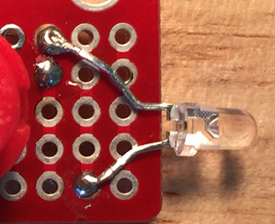
On an LED there is a positive and negative side which are quite important since the LED only lights up in one direction. The positive lead is the longer one (because it takes more ink to make a + sign) but that only helps until you cut it off:) In the image above the positive lead is the lower one and if you look carefully inside the LED you can see the asymmetry in the inside as well. Gently shape the leads of the LED so they will go through the holes shown on the front side. Leave the ends long on the back when you solder them (we will finish them off in a couple of steps). Notice that the negative (short) lead is next to the white wire you installed in the first step.
The Switch:
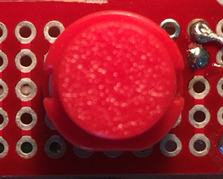
This is the momentary switch. It turns off if you don't hold it down which is good since it is easy to run the battery down and they are not cheap. Look carefully at the switch and you will notice that there are two notches that must be oriented as shown. Place the switch in the center one row behind the negative lead of the LED. Turn the board over and solder all 4 pins.
Last Step!!!!

Being very careful that you know which lead you're cutting trim the negative (-) lead of the LED next to the white wire. Then, on the back side, gently bend the positive lead (at the top in the picture) down until it touches the pin of the switch. Solder the positive lead of the LED to the pin and you're done!
Inspect all of your solder connections and look at others as well to test your perception.
Install battery and test!
