Op Amp Lab:
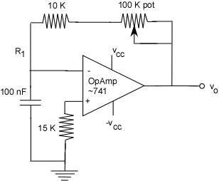
It is very interesting to be looking at this fresh again this year trying to figure out what I want you to get out of this. This will be a little different application that is drawn from the OSU ENGR 201 lab manual. You will need to do a number of things during this lab including look up spec sheets and think about what all this means. Here's the starting point:

Commentary:
Build your circuit on your small prototyping boards so that you can take it with you and not leave it lying around between classes.
The op amps I have available are LF353N's (or perhaps others), which contain two op amps in a single package. You must search online and find a data sheet for the device you choose. You will need this to determine which pins you are going to hook up to everything.
All the Vcc's should be the same voltage though one is + and one is -. Look at the spec sheet to understand what the minimums are. We will use the adjustable power supplies on the powered prototyping boards to provide Vcc.
A pot is not a medical therapy but rather an adjustable resistor. This section of the circuit acts to set a reference point (voltage) which you can control. You will need to determine how the legs of the 100k pot are connected and how to control it's behavior. I will give you a pot (short for potentiometer) to look at and measure as a voyage of discovery.
Once you have the circuit wired up you should grab and oscilloscope and take a look at the signal at the inverting input of the op amp and at the output. You will find these traces critical in constructing an understanding of what is going on.
This circuit is supposed to begin oscillating on it's own as soon as it is powered up. I will be expecting a clear conceptual analysis in your notebook that clearly displays your understanding of why this happens.
Process:
1) Read the commentary, find the spec sheets, and analyze the circuit.
2) Build the circuit on your mini project board leaving a clear connection point for the thermistor which has banana plugs on the ends.
3) Allow me to check your circuit and your calculations before attaching it to the powered project board.
4) Test your circuit to see if it is performing according to the requirements. Your notebook will contain beautiful quantified sketches of the oscilloscope traces at the inverting input and the output.
5) Constuct and clear and eloquent verbal/conceptual description of why the circuit oscillates that is consistent with our discussions of the behavior of op amps in class.
6) Demonstrate that your circuit meets the requirements stated and receive your just accolades:)
