Oscilloscopes and RC Circuits:
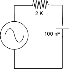
Now that you've learned how to use an oscilloscope in some general fashion lets apply it to making a measurement of a circuit. In this case you will be introduced to a very simple resistor/capacitor circuit that is sometimes used in speaker circuits.
The Circuit:
In a separate corner of your project board build the following circuit. The function generator will provide the variable voltage source so you'll have to figure out how to connect it to the circuit.

You will find the BNC to grippers adapter very useful in connecting the function generator to the circuit.
Measurements:
1) Set up your function generator to provide a 2 V peak to peak sine wave with no DC offset. Check this at several frequencies using the oscilloscope. You should find that the frequency you choose doesn't affect the peak to peak voltage.
2) Set your oscilloscope up to measure the voltage drop across the capacitor. Again you will find that the other set of BNC to grippers adaptor will be very handy. Measure and plot (at least 10 points) the amplitude of the voltage drop across the capacitor from 100 Hz to 100 kHz. Now measure and plot the voltage drop across the resistor as a function of frequency.
3) Reverse the locations of the resistor and the capacitor. Now measure and plot (on the same plot) the voltage drop across the resistor (shouldn't have to move the oscilloscope leads) for the same range of frequencies.
4) Based on the data on your plots (which are beautifully sketched in your notebooks:) which of these circuits functions as a "low pass filter" and which is a "high pass filter"? Explain your reasoning. Why might this be useful in speaker systems?
5) Increase either the resistor or the capacitor by a factor of 20 and repeat one of the data sets. What has changed and what does this mean?
