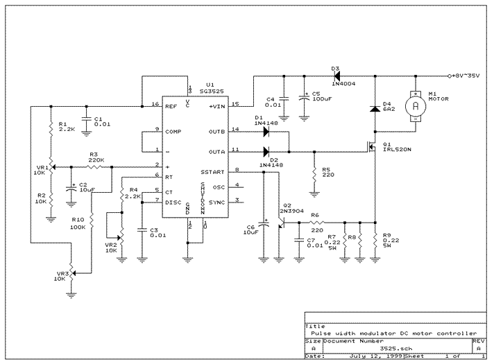
This term the lab activities will be constructed around the following circuit which is intended to control the speed of a DC motor by sensing some external characteristic like temperature. Sounds like something we could use in many settings doesn't it. This is provided as a general reference along with some useful links for your personal edification.

This control circuit is ideal for the accurate control of DC motors as well as other applications like lighting levels and small heaters etc. The circuit converts a DC voltage into series of pulses, such that the pulse duration is directly proportion to the value of the DC voltage. The great advantage of such a circuit is that almost no power is lost in the control circuit. This circuit protects against overload and short circuit, PWM range can be adjusted from 0-100%, PWM frequency is 100HZ-5KHZ adjustable. Operation voltage from +8V~ 35V, minimum current consumption is about 35mA. Maximum current can go up to 6.5A. Efficiency better than 90% at full load. The functions of three trim pots are as follow: VR1: setting the minimum output voltage VR3: setting the maximum output voltage VR2: setting the output frequency.
Here is a good introduction to the basic ideas of PWM motor controllers. I found it quite useful though it's frustrating to be excluded from the other obviously useful documents. Happy reading:)
Here's another speed controller link that has good explanations of what's going on. See what you think.
