Equipment Checkout:
In this course we will have numerous opportunities to use equipment to verify the behavior of simple circuits. In this exploration you will be introduced to several new pieces of equipment that you may not have used before. This equipment is commonly used in science and engineering labs around the world. As a result it seems like it would be good if you could turn them on and use them for simple tasks without damaging yourself or the equipment. In particular you will be learning to use an oscilloscope and a function generator.
Oscilloscope:
The oscilloscope comes in many forms and the model we will use is a digital version of the classic analog "Oscope" which displays the voltage at up to two points in the circuit as a function of time (this is called a trace). Our PC based scope will also store and allow analysis of the trace in a manner very similar to the way you analyze functions on your calculators.
Function Generator:
The function generator is used to provide specific signals (voltage patterns) that replicate types of signals your circuit may be used to process. Typically function generators allow you to send signals which have the form of sine waves, square waves, and triangular shaped waves through your circuit. You can adjust the frequency of this signal from around 10 Hz to 100 kHz. This signals replicate acoustic patterns like those found in stereo systems, digital data streams like those found in computers, and a variety of data types that might be collected many experiments.
Connectors:
For a variety of reasons we have to be more careful than usual in passing these signals from one location to another. To do this it is common to use some form of coaxial cable in which a central wire which carries the signal is surrounded by a second conductor. This second conductor is insulated from the signal wire and forms a shield around it (this is usually connected to ground - 0 V) which isolates the signal being carried from electrical interference in the surrounding environment. The connectors on the ends of these cables connect to both the central signal wire and the shield. These connectors come in many forms the most common of which are called BNC connectors. You will here such such cables refered to as BNC cables, coax cables, or shielded cables.
Procedure:
Turning them on:
Both oscilloscopes and function generators are relatively immune to damage as long as you don't connect them to anything. What this means is you can always check to make sure they work at a basic level by making sure that they are disconnected from any cables and then plugging them in and turning them on. Power switches and buttons take many forms and styles but are usually on the front. When you power them up you should see some indicator light which indicates the presence of power but there may be few other indicators of life. If the indicator light doesn't come on and you did remember to plug it in then consider the possibility that the main fuse has been blown. This is one of the more common problems and it is real irritating if you don't think to check it. The main fuse is usually located where the power cord enters the equipment at the back. (Do you know how to check a fuse?)
Hooking them up:
With the power on the oscilloscope and the function generator off locate the signal output connector on the function generator and the signal inputs on the oscilloscope. You will notice that these connectors are a little different that those you may have encountered before. Find a BNC cable of suitable length and connect the output of the function generator to the left input of the oscilloscope. There are normally multiple outputs from function generators which include TTL, HI, and LO. The TTL output is specifically designed for use with digital logic circuits. The HI and LO outputs allow some choice for the peak to peak voltage of the signal being generated. For most introductory applications the HI output is the most appropriate.
Setting the function generator:
On the face of the function generator (see figure below) are usually a several sets of switches (sometimes many switches) and rotatable dial. These days our function generators tend to have digital read outs which suggest greater accuracy but you need to be able to check it. One set of switches is used to set the general range of the frequency of the signal being generated (often by factors of 10). The rotating dial/knob is used to select the specific signal frequency desired. Another set of switches is used to select the form of the signal being generated from sine waves to square waves and sometimes other forms. Set your function generator to produce a 2 kHz sine wave. Do not turn the power on yet!
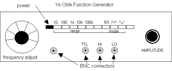
Further searching will lead to another small knob which is usually labeled "amplitude" or "amp" or "sig level". This controls the strength of the signal being generated by increasing the voltage. In our case this should be set to the middle of its range. In general you might want to set this quite low until you are sure the circuit you are testing can handle the signal strength.
Have your instructor check your set up of the function generator.
Setting up the oscilloscope:
You may wish to read through some oscilloscope tutorials (links below) from other institutions. Be aware the part of the fun is that different models of scopes tend to label and position the controls differently even though the functionality is pretty much universal. There are an enormous number of video tutorials on the web which all go through most of the same material. The screen display for our PCSU1000 devices is structured to look very similar to the standard analog "face" that you would meet in the lab. The primary differnce is that we won't be using 10X probes.
At this point the PCSU1000 software is in Class Application/Science/ on the lab computers. Plug in the oscilloscope base unit (USB port on tower NOT screen) before starting up the software. You should see the power light come on if everything works as anticipated.
Oscilloscope Tutorial - this one's pretty nice, those British don't you know!
Turn on both the oscilloscope (first) and the function generator. (remember that they are now connected to each other) On most oscilloscopes there will be a knob which is labeled as the "time scale" or "horizontal" which you should find and set to 1 ms/div. This means that each major horizontal division on the screen of the oscilloscope will correspond to 1 ms.
There will also be one or more knobs which are labeled "volts" or "vertical scale". When you find this knob you will note that there is a x1 and a x10 notation on the dial. Set the vertical scale on channel 1 (the left input) so that it reads 2 V/div by the x1 notation. This means that each vertical division on the oscilloscope display will correspond to 2 V. (The x10 notation indicates the vertical scale in the event you are using a x10 probe which magnifies the signal going to the oscilloscope) At this point you may or may not see anything happening on the screen of the oscilloscope. If you do ignore it while we continue with the set up.
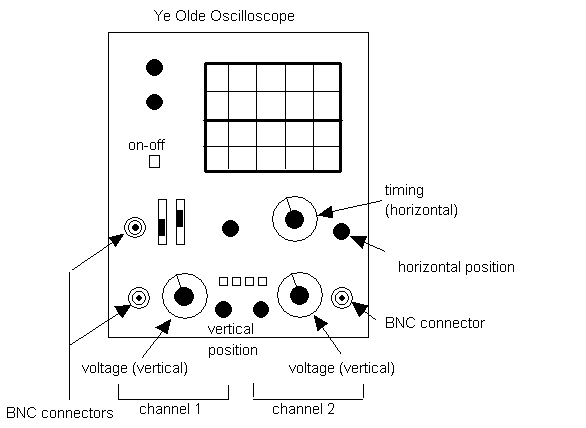
Near the vertical scale knob there is usually a switch which has three settings - AC, Gnd, and DC. These refer to the types of signals you are asking the oscilloscope to consider. For our purposes today set the switch to AC.
Finally we need to locate the cause of most of the problems and frustrations in using the oscilloscope. The control panel for triggering is normally located in a separate part of the front panel. The triggering module tells the oscilloscope when to start displaying the signal coming in. The triggering module contains a switch that offers two choices - internal or external. For our purposes start by setting the switch to internal triggering. Under these circumstances the oscilloscope will decide for itself when to begin displaying the data. At this point if all is well you should now see some sort of sine wave flashing across your oscilloscope screen. If your screen is still blank have your instructor examine the situation and sit back and enjoy your first experience with "Scope Frustration!"
It is likely that the display will be very unstable looking and hard to watch.This is because the scope is triggering on its own internal schedule which leads to successive traces starting at different points on the signal pattern. Since these successive traces happen very rapidly the display looks very unpleasant. The solution to this display problem is to use an external trigger that allows you to telll the scope when to trigger the next trace.
Now set the trigger switch to external. When you are triggering externally you need to provide a signal to the scope to tell it when to start a trace.The actual information the oscilloscope uses is the trigger voltage and slope. When the trigger crosses a particular voltage set by the trigger level knob it begins to display the signal on the screen. When it runs out of screen the oscilloscope stops and waits for the trigger to cross the magic threshold again. This leads to difficulties if the signal never crosses the voltage threshold. A very effective way to trigger the scope is to use the signal from the function generator. To do this we need to divide the signal coming from the function generator and connect it to the external trigger. To do this use a T connector and another piece of BNC cable.
Once you have a steady display on your oscilloscope you are ready to make a couple of quick measurements.
Measurements:
1) Adjust your function generator frequency until the oscilloscope verifies that signal from the function generator has a frequency of 2.5 kHz. Do this by measuring the period of the signal being displayed on the scope. (You will need to calculate the period of a 2.5 kHz wave!)
2) Adjust the signal level from the function generator until the sine wave being displayed has a peak to peak amplitude of 3 V. Get a DMM and measure the AC voltage and compare it to what you measure. Why is it the same or different than what the scope tells you?
3) Use the oscilloscope to determine the frequency and amplitude of an arbitrary sine wave selected by your instructor.
4) Use the oscilloscope to determine the frequencies and amplitudes of a potential mixture of sine functions provided by your evil instructor using an old school analog scope.
Certification:
This certifies that ________________________ has been checked out on the basic use of the oscilloscope and the function generator. This includes the ability to turn on and connect both devices and determine the frequency and amplitude of a signal without damaging themselves or the equipment.
__________________________
Dr. Bruce Emerson:)
