Note: I would normally expect to complete this lab in 1 session. In the world of remote teaching/learning and a large class that may be an optimistic vision. If we need to extend the time for this lab we will do so but let's hope my documentation is clear enough that you'll be all done before we even get together for the lab.
Purpose:
Your Qbot is based on a open source microprocessor board called an Arduino. That's why you downloaded and installed the Arduino IDE software for the previous lab. In this lab we need to make sure you can use that software to 'talk' to your Qbot and give it some specific instructions. You will find if you look at Arduino tutorials across the globe the classic place these all start is with a sketch (which is just the word the Arduino community uses to describe a program) that makes a little light blink. The sketch is usually called Blink but I prefer Blinky instead.
While you may be anxious about writing code please try not to worry. We will take small steps, answer your questions, and give you examples and frameworks to work with. Before we get started let me just point out a visual tool that is intended to help you. When I share code with you it will be inside what looks like a lightly colored box and indented. Here is an example...
for (int thisPin = 0; thisPin < 6; thisPin++) {
     digitalWrite(myPins[thisPin], HIGH);
     delay(500);
     digitalWrite(myPins[thisPin], LOW);
     delay(500);
}
You can select and copy this code (we'll do this later) and paste it directly into your Arduino sketch. You may have to do some formatting but the code will work. Watch for these code windows in the lab. They are there to make things easier for you. Be careful...you won't need all of them but I will use them to distinguish code from other text.
Procedure:
This is likely to be a long set of instructions since I want to be sure to minimize confusions (taking a cue from our lab last week). I hope that you might be able to complete the lab without any input from me but don't stress if you get stuck at some point. Just come to the lab class meeting or email me.
- After working on this for a while I realized I need to separate out the startup instructions for the Qbot and the Arduino IDE. (Qbot startup, Arduino IDE startup) When you complete these steps you should have your Qbot charging and the IDE talking to your Qbot successfully. Then we will be ready for the next step.
- With the power off on your Qbot load (the right arrow at the top of the Blink sketch) the Blink sketch to your Qbot. You should see the little blue LEDs flash and then stay off. After the blue LEDs go off you should see a little red LED pulsing slowly next to the power switch. This is the same as step 5 of the IDE startup process. If all that is good then go on to the next step.
- In this step we will learn to understand the structure of an Arduino sketch and change the rate at which the little red LED flashes. This is a relatively long step so plan ahead. Here is the guide to making your first customized sketch!
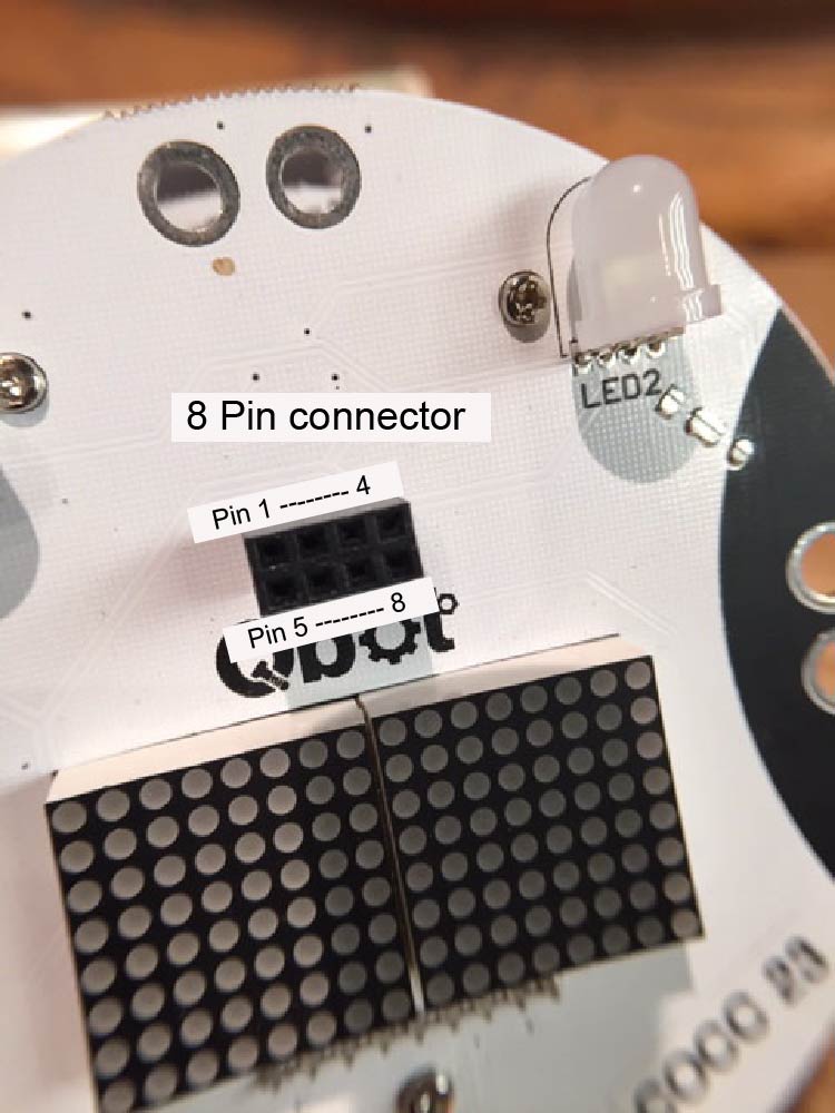
- You will notice that if you turn the Qbot on (the sliding power switch) the little red LED stops flashing and different things happen. This is because the Qbot is wired slightly differently than a traditional Arduino and when it is on pin 13 is NOT connected to the little red LED. To be able to have a light flash when the Qbot is on we need to use a different pin. To do this we first need to remove the 'eyes' on top of the Qbot. To do this grasp it gently on each side of the 'eyes' and pull up to remove the 4 pins from the connector on top of the Qbot. Set it aside where it will not get dropped or stepped on to protect the 'eyes' and the pins from bending.
- In your kit you have an LED with two wires attached to it. One leg has a black wrapping on it that covers a resistor. The resistor is there to protect both the LED and the Qbot from harm. If, during the course of the term, the wires or resistor break off please let me know so we can fix them. As you look at the connector that you removed the 'eyes' from you will see it has two rows of 4 holes. Those female pins match the size of the male pins attached to your LED. When you're looking forwards at the Qbot the pins of this connector are numbered 1 to 4 from left to right across the front and 5 - 8 from left to right across the back. Place the LED wire (this is the + pin) with resistor (which one is that?) in the front right hole (pin 4) and the other LED wire (this is the - pin) in the front left hole (pin 1).

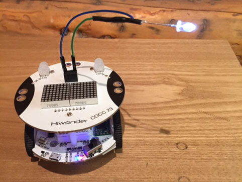
- Verify that when you turn on the power to the Qbot the LED comes on without flashing. Turn off the power, reverse the locations of the LED pins (+ to pin 1 and - to pin 4), and turn the power back on. What do you observe? What does this mean? It could mean that the LED is broken which you can check by switching the LED pins back (after powering down and back up). The take home message here is that LED's only work when they are hooked up in the 'right' direction. Remember this because it is common to get LED's hooked up in the wrong direction and if it's not doing what you expect try reversing the LED pins. Here's what mine looks like with the LED on.

- You previously modified the Blink sketch and saved it as QBlink. We did this so we can more easily choose which pin to control with the sketch. Go back to your QBlink sketch and change the testpin from 13 to 3. It turns out pin 3 of the Arduino is connected to pin 3 of the 8 pin connector on the top of the Qbot. If you load the new version of QBlink, move the + pin of the LED to pin 3 of the connector (one to the left of where it was) , and turn the Qbot on you should see the white LED flash under your control.
- Show someone in your house that you can control the rate at which the red LED (pin 13) flashes. Show them you can control the rate at which the white LED (pin 3) flashes when connected properly to the 8 pin connector on top of the Qbot.This person will be asked to verify your success for your lab report!
LAB DELIVERABLES: (Turn in on Bb)
I) Paste your QBlink code into a word document with the usual header information at the top showing that you have modified the blink rate of the white LED connected to pin 3.
II) Add a scan or photograph of the statement below (you will have to embed this in your word document) from someone I should believe. The statement can be handwritten if access to printers is a challenge.
I [print signer's name] attest that [student name] has demonstrated to me that they can control the flashing of a little red LED on the bottom level of the Qbot and the flashing of an external white LED plugged into a black connector on top of the Qbot where the eyes used to be.
Signed [signature]
Dated [date]
